
This article is part of a web dev tech series from Microsoft. Thank you for supporting the partners who make SitePoint possible.
You may have noticed that we first talked a lot about babylon.js last year and most recently we’ve released babylon.js v2.0 with 3D sound positioning (with WebAudio) and volumetric light scattering.
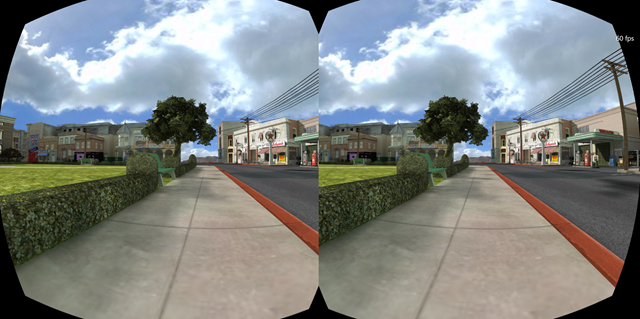
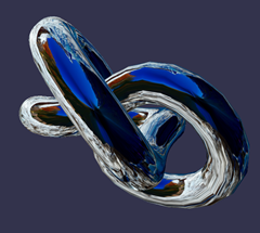
If you missed the v1.0 announcement, first you can catch-up with the keynote for day two here and go directly to 2:24-2:28. In it, Microsoft evangelists Steven Guggenheimer and John Shewchuk demoed how the Oculus Rift support was added to Babylon.js. And one of the key things for this demo was the work we did on a specific shader to simulate lenses as you can see in this picture:
I also presented a session with Frank Olivier and Ben Constable about graphics on IE and Babylon.js
This leads me to one of the questions I often have about babylon.js: What do you mean by shaders? So today I am going to try to explain to you how shaders work.
Key Takeaways
- Definition and Role of Shaders: Shaders are specialized programs used in WebGL and HTML5 to determine the rendering of light and color on 3D objects, enhancing visual effects and realism in graphics.
- Creation with WebGL: Shaders are written in GLSL (OpenGL Shading Language) and executed on the GPU, requiring a series of steps including compiling and linking code to a WebGL context on a canvas element.
- Types of Shaders: There are primarily two types of shaders in WebGL; vertex shaders that manage vertex attributes, and fragment shaders that handle pixel attributes, allowing for detailed manipulation of graphics.
- Application in Game Development: Shaders are crucial in game development for creating dynamic visual effects such as realistic lighting, water simulation, and landscape generation.
- Learning and Challenges: Writing shaders involves a deep understanding of computer graphics and GLSL, with resources available online for learning. However, debugging shaders can be complex due to limited specialized debugging tools.
- Performance and Limitations: Utilizing shaders can significantly boost the performance of web applications by leveraging GPU processing, though they are restricted from accessing DOM or other web APIs and have limited data type support.
The Theory
Before starting experimenting, we must first see how things work internally.
When dealing with hardware accelerated 3D, we are discussing two CPUs: the main CPU and the GPU. The GPU is a kind of extremely specialized CPU.
The GPU is a state machine that you set up using the CPU. For instance the CPU will configure the GPU to render lines instead of triangles. Or it will define that transparency is on and so on.
Once all the states are set, the CPU will define what to render (the geometry, which is composed of a list of points (called the vertices and stored into an array called vertex buffer) and a list of indexes (the faces — or triangles — stored into an array called index buffer)).
The final step for the CPU is to define how to render the geometry and for this specific task, the CPU will define shaders for the GPU. Shaders are a piece of code that the GPU will execute for each of the vertices and pixels it has to render.
First some vocabulary: think of a vertex (vertices when there are several of them) as a “point” in a 3D environment as opposed to the point in a 2D environment.
There are two kinds of shaders: vertex shader and pixel (or fragment) shader.
Graphics pipeline
Before digging into shaders, let’s take a step back. To render pixels the GPU will take the geometry defined by the CPU and will do the following:
-
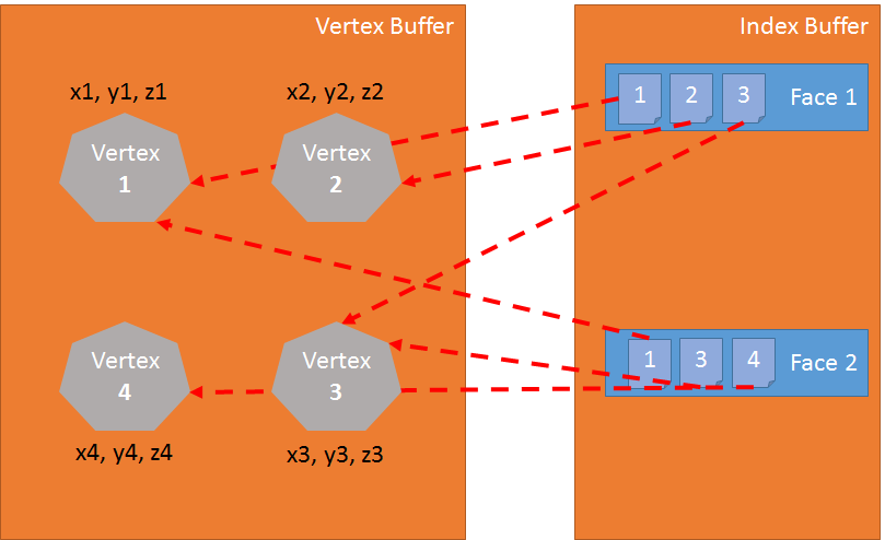
Using the index buffer, three vertices are gathered to define a triangle: the index buffer contains a list of vertex indexes. This means that each entry in the index buffer is the number of a vertex in the vertex buffer. This is really useful to avoid duplicating vertices. For instance the following index buffer is a list of 2 faces: [1 2 3 1 3 4]. The first face contains vertex 1, vertex 2 and vertex 3. The second face contains vertex 1, vertex 3 and vertex 4. So there are 4 vertices in this geometry:
-
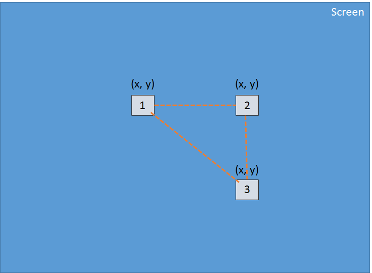
The vertex shader is applied to each vertex of the triangle. The primary goal of the vertex shader is to produce a pixel for each vertex (the projection on the 2D screen of the 3D vertex):
-
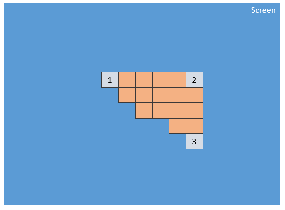
Using these 3 pixels (which define a 2d triangle on the screen), the GPU will interpolate all values attached to the pixel (at least its position) and the pixel shader will be applied to every pixel included into the 2d triangle in order to generate a color for every pixel:
-
This process is done for every face defined by the index buffer.
Obviously due to its parallel nature, the GPU is able to process this step for a lot of faces simultaneously and then achieve really good performance.
GLSL
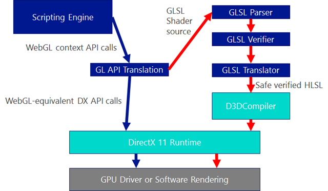
We have just seen that to render triangles, the GPU needs two shaders: the vertex shader and the pixel shader. These shaders are written using a language called GLSL (Graphics Library Shader Language). It looks like C.
For Internet Explorer 11, we have developed a compiler to transform GLSL to HLSL (High Level Shader Language) which is the shader language of DirectX 11. This allows IE11 to ensure that the shader code is safe (You don’t want to reset your computer when using WebGL):
precision highp float;
// Attributes

attribute vec3 position;

attribute vec2 uv;
// Uniforms

uniform mat4 worldViewProjection;
// Varying

varying vec2 vUV;
void main(void) {

    gl_Position = worldViewProjection * vec4(position, 1.0);
    vUV = uv;

}
Vertex shader structure
A vertex shader contains the following:
- Attributes: An attribute defines a portion of a vertex. By default a vertex should at least contain a position (a
vector3:x, y, z). But as a developer you can decide to add more information. For instance in the former shader, there is avector2nameduv(Texture coordinates that allows to apply a 2D texture on a 3D object) - Uniforms: A uniform is a variable used by the shader and defined by the CPU. The only uniform we have here is a matrix used to project the position of the vertex (x, y, z) to the screen (x, y)
- Varying: Varying variables are values created by the vertex shader and transmitted to the pixel shader. Here the vertex shader will transmit a
vUV(a simple copy ofuv) value to the pixel shader. This means that a pixel is defined here with a position and a texture coordinates. These values will be interpolated by the GPU and used by the pixel shader. - main: The function named main is the code executed by the GPU for each vertex and must at least produce a value for gl_position (the position on the screen of the current vertex).
We can see in our sample that the vertex shader is pretty simple. It generates a system variable (starting with gl_) named gl_position to define the position of the associated pixel and it sets a varying variable called vUV.
The voodoo behind matrices
In our shader we have a matrix named worldViewProjection. We use this matrix to project the vertex position to the gl_position variable. That is cool, but how do we get the value of this matrix? It is a uniform so we have to define it on the CPU side (using JavaScript).
This is one of the complex parts of doing 3D. You must understand complex math (or you will have to use a 3D engine like babylon.js that we are going to see later).
The worldViewProjection matrix is the combination of 3 different matrices:
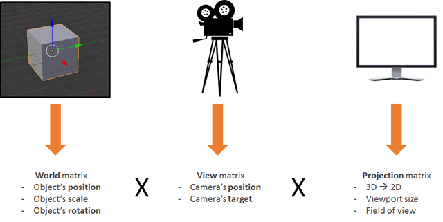
Using the resulting matrix allows us to be able to transform 3d vertices to 2d pixels while taking into account the point of view and everything related to the position/scale/rotation of the current object.
This is your responsibility as a 3D developer: to create and keep this matrix up to date.
Back to the shaders
Once the vertex shader is executed on every vertex (three times then) we have three pixels with a correct gl_position and a _vUV _value. The GPU will then interpolate these values on every pixel contained in the triangle produced by these pixels
Then for each pixel, it will execute the pixel shader:
precision highp float;

varying vec2 vUV;

uniform sampler2D textureSampler;
void main(void) {

    gl_FragColor = texture2D(textureSampler, vUV);

}
Pixel (or fragment) shader structure
The structure of a pixel shader is similar to a vertex shader:
- Varying: Varying variables are values created by the vertex shader and transmitted to the pixel shader. Here the pixel shader will receive a vUV value from the vertex shader.
- Uniforms: A uniform is a variable used by the shader and defined by the CPU. The only uniform we have here is a sampler which is a tool used to read texture colors.
- main: The function named main is the code executed by the GPU for each pixel and must at least produce a value for
gl_FragColor(The color of the current pixel).
This pixel shader is fairly simple: It reads the color from the texture using texture coordinates from the vertex shader (which in turn got it from the vertex).
Do you want to see the result of such a shader? Here it is:

(You can see the full working code on my blog here)
To achieve this result, you will have to deal with a LOT of WebGL code. Indeed, WebGL is a really powerful but really low level API and you have to do everything by yourself, from creating the buffers to defining vertex structures. You also have to do all the math and set all the states and handle texture loading and so on…
Too hard? BABYLON.ShaderMaterial to the Rescue
I know what you are thinking: shaders are really cool, but I do not want to bother with WebGL internal plumbing or even with math.
And you are right! This is a perfectly legitimate ask and that is exactly why I created Babylon.js.
Let me present you the code used by the previous rolling sphere demo. First of all you will need a simple webpage:
< !DOCTYPE html>

<html>

<head>

    <title>Babylon.js</title>

    <script src="Babylon.js"></script>
    <script type="application/vertexShader" id="vertexShaderCode">

        precision highp float;
        // Attributes

        attribute vec3 position;

        attribute vec2 uv;
        // Uniforms

        uniform mat4 worldViewProjection;
        // Normal

        varying vec2 vUV;
        void main(void) {

            gl_Position = worldViewProjection * vec4(position, 1.0);
        vUV = uv;

        }

    </script>
    <script type="application/fragmentShader" id="fragmentShaderCode">

        precision highp float;

        varying vec2 vUV;
        uniform sampler2D textureSampler;
        void main(void) {

            gl_FragColor = texture2D(textureSampler, vUV);

        }

    </script>
    <script src="index.js"></script>

    <style>

        html, body {

            width: 100%;

            height: 100%;

            padding: 0;

            margin: 0;

            overflow: hidden;

            margin: 0px;

            overflow: hidden;

        }
        #renderCanvas {

            width: 100%;

            height: 100%;

            touch-action: none;

            -ms-touch-action: none;

        }

    </style>

</head>

<body>

    <canvas id="renderCanvas"></canvas>

</body>

</html>
You will notice that the shaders are defined by script tags. With Babylon.js you can also define them in separated files (.fx files).
You can get babylon.js here or on our GitHub repo. You must use version 1.11 or higher to get access to BABYLON.StandardMaterial.
And finally the main JavaScript code is the following:
"use strict";
document.addEventListener("DOMContentLoaded", startGame, false);
function startGame() {

    if (BABYLON.Engine.isSupported()) {

        var canvas = document.getElementById("renderCanvas");

        var engine = new BABYLON.Engine(canvas, false);

        var scene = new BABYLON.Scene(engine);

        var camera = new BABYLON.ArcRotateCamera("Camera", 0, Math.PI / 2, 10, BABYLON.Vector3.Zero(), scene);
        camera.attachControl(canvas);
        // Creating sphere

        var sphere = BABYLON.Mesh.CreateSphere("Sphere", 16, 5, scene);
        var amigaMaterial = new BABYLON.ShaderMaterial("amiga", scene, {

            vertexElement: "vertexShaderCode",

            fragmentElement: "fragmentShaderCode",

        },

        {

            attributes: ["position", "uv"],

            uniforms: ["worldViewProjection"]

        });

        amigaMaterial.setTexture("textureSampler", new BABYLON.Texture("amiga.jpg", scene));
        sphere.material = amigaMaterial;
        engine.runRenderLoop(function () {

            sphere.rotation.y += 0.05;

            scene.render();

        });

    }

};
You can see that I use a BABYLON.ShaderMaterial to get rid of all the burden of compiling, linking and handling shaders.
When you create a BABYLON.ShaderMaterial, you have to specify the DOM element used to store the shaders or the base name of the files where the shaders are. If you choose to use files, you must create a file for each shader and use the following pattern basename.vertex.fx and basename.fragment,.fx. Then you will have to create the material like this:
var cloudMaterial = new BABYLON.ShaderMaterial("cloud", scene, "./myShader",{

            attributes: ["position", "uv"],

            uniforms: ["worldViewProjection"]

        });
You must also specify the name of attributes and uniforms that you use.
Then you can set directly the value of your uniforms and samplers using setTexture, setFloat, setFloats, setColor3, setColor4, setVector2, setVector3, setVector4, setMatrix functions.
Do you remember the previous worldViewProjection matrix? Using Babylon.js and BABYLON.ShaderMaterial, you have nothing to worry about it! The BABYLON.ShaderMaterial will automatically compute it for you because you declare it in the list of uniforms. BABYLON.ShaderMaterial can also handle the following matrices for you:
- world
- view
- projection
- worldView
- worldViewProjection
No need for math any longer. For instance each time you execute sphere.rotation.y += 0.05, the world matrix of the sphere is generated for you and transmitted to the GPU.
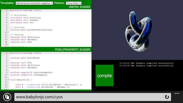
CYOS: Create Your Own Shader
So let’s go bigger and create a page where you can dynamically create your own shaders and see the result immediately. This page is going to use the same code that we previously discussed and is going to use BABYLON.ShaderMaterial object to compile and execute shaders that you will create.
I used ACE code editor for CYOS. This is an incredible code editor with syntax highlighters. Feel free to have a look at it here. You can find CYOS here.
Using the first combo box, you will be able to select pre-defined shaders. We will see each of them right after.
You can also change the mesh (the 3D object) used to preview your shaders using the second combo box.
The compile button is used to create a new BABYLON.ShaderMaterial from your shaders. The code used by this button is the following:
// Compile

shaderMaterial = new BABYLON.ShaderMaterial("shader", scene, {

    vertexElement: "vertexShaderCode",

    fragmentElement: "fragmentShaderCode",

},

    {

        attributes: ["position", "normal", "uv"],

        uniforms: ["world", "worldView", "worldViewProjection"]

    });
var refTexture = new BABYLON.Texture("ref.jpg", scene);

refTexture.wrapU = BABYLON.Texture.CLAMP_ADDRESSMODE;

refTexture.wrapV = BABYLON.Texture.CLAMP_ADDRESSMODE;
var amigaTexture = new BABYLON.Texture("amiga.jpg", scene);
shaderMaterial.setTexture("textureSampler", amigaTexture);

shaderMaterial.setTexture("refSampler", refTexture);

shaderMaterial.setFloat("time", 0);

shaderMaterial.setVector3("cameraPosition", BABYLON.Vector3.Zero());

shaderMaterial.backFaceCulling = false;
mesh.material = shaderMaterial;
The material is ready to send you three pre-computed matrices (world, worldView and worldViewProjection). Vertices will come with position, normal and texture coordinates. Two textures are also already loaded for you:
And finally here is the renderLoop where I update two convenient uniforms:
- One called
timein order to get some funny animations - One called
cameraPositionto get the position of the camera into your shaders (will be useful for lighting equations)
engine.runRenderLoop(function () {

    mesh.rotation.y += 0.001;
    if (shaderMaterial) {

        shaderMaterial.setFloat("time", time);

        time += 0.02;
        shaderMaterial.setVector3("cameraPosition", camera.position);

    }
    scene.render();

});
Thanks to the work we did on Windows Phone 8.1, we can also use CYOS on your Windows Phone (It is always a good time to create shaders):
Basic shader
So let’s start with the very first shader defined on CYOS: The Basic shader.
We already know this shader. It computes the gl_position and uses texture coordinates to fetch a color for every pixel.
To compute the pixel position we just need the worldViewProjection matrix and the vertex’s position:
precision highp float;
// Attributes

attribute vec3 position;

attribute vec2 uv;
// Uniforms

uniform mat4 worldViewProjection;
// Varying

varying vec2 vUV;
void main(void) {

    gl_Position = worldViewProjection * vec4(position, 1.0);
    vUV = uv;

}
Texture coordinates (uv) are transmitted unmodified to pixel shader.
Please note that we need to add precision mediump float; on the first line for both vertex and pixel shaders because Chrome requires it. It defines that, for better performance, we do not use full precision floating values.
The pixel shader is even simpler because we just need to use texture coordinates and fetch a texture color:
precision highp float;
varying vec2 vUV;
uniform sampler2D textureSampler;
void main(void) {

    gl_FragColor = texture2D(textureSampler, vUV);

}
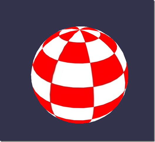
We saw previously that the textureSampler uniform is filled with the “amiga” texture so the result is the following:
Black and white shader
Now let’s continue with a new shader: the Black and white shader.
The goal of this shader is to use the previous one but with a black and white only rendering mode.
To do so we can keep the same vertex shader. The pixel shader will be slightly modified.
The first option we have is to take only one component like for instance the green one:
precision highp float;
varying vec2 vUV;
uniform sampler2D textureSampler;
void main(void) {

    gl_FragColor = vec4(texture2D(textureSampler, vUV).ggg, 1.0);

}
As you can see instead of using .rgb (this operation is called a swizzle) we used .ggg.
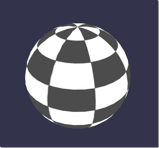
But if we want a really accurate black and white effect, it should be a better idea to compute the luminance (which takes in account all components):
precision highp float;
varying vec2 vUV;
uniform sampler2D textureSampler;
void main(void) {

    float luminance = dot(texture2D(textureSampler, vUV).rgb, vec3(0.3, 0.59, 0.11));

    gl_FragColor = vec4(luminance, luminance, luminance, 1.0);

}
The dot operation (or dot product) is computed like this:
result = v0.x * v1.x + v0.y * v1.y + v0.z * v1.z
So in our case:
luminance = r * 0.3 + g * 0.59 + b * 0.11 (This values are based on the fact that human eye is more sensible to green)
Sounds cool, doesn’t it?
Cell Shading shader
Now let’s move to a more complex shader: the Cell shading shader.
This one will require to get the vertex’s normal and the vertex’s position in the pixel shader. So the vertex shader will look like this:
precision highp float;
// Attributes

attribute vec3 position;

attribute vec3 normal;

attribute vec2 uv;
// Uniforms

uniform mat4 world;

uniform mat4 worldViewProjection;
// Varying

varying vec3 vPositionW;

varying vec3 vNormalW;

varying vec2 vUV;
void main(void) {

    vec4 outPosition = worldViewProjection * vec4(position, 1.0);

    gl_Position = outPosition;
    vPositionW = vec3(world * vec4(position, 1.0));

    vNormalW = normalize(vec3(world * vec4(normal, 0.0)));
    vUV = uv;

}
Please note that we also use the world matrix because position and normal are stored without any transformation and we must apply the world matrix to take in account object’s rotation.
The pixel shader is the following:
precision highp float;
// Lights

varying vec3 vPositionW;

varying vec3 vNormalW;

varying vec2 vUV;
// Refs

uniform sampler2D textureSampler;
void main(void) {

    float ToonThresholds[4];

    ToonThresholds[0] = 0.95;

    ToonThresholds[1] = 0.5;

    ToonThresholds[2] = 0.2;

    ToonThresholds[3] = 0.03;
    float ToonBrightnessLevels[5];

    ToonBrightnessLevels[0] = 1.0;

    ToonBrightnessLevels[1] = 0.8;

    ToonBrightnessLevels[2] = 0.6;

    ToonBrightnessLevels[3] = 0.35;

    ToonBrightnessLevels[4] = 0.2;
    vec3 vLightPosition = vec3(0, 20, 10);
    // Light

    vec3 lightVectorW = normalize(vLightPosition - vPositionW);
    // diffuse

    float ndl = max(0., dot(vNormalW, lightVectorW));
    vec3 color = texture2D(textureSampler, vUV).rgb;
    if (ndl > ToonThresholds[0])

    {

        color *= ToonBrightnessLevels[0];

    }

    else if (ndl > ToonThresholds[1])

    {

        color *= ToonBrightnessLevels[1];

    }

    else if (ndl > ToonThresholds[2])

    {

        color *= ToonBrightnessLevels[2];

    }

    else if (ndl > ToonThresholds[3])

    {

        color *= ToonBrightnessLevels[3];

    }

    else

    {

        color *= ToonBrightnessLevels[4];

    }
    gl_FragColor = vec4(color, 1.);

}
The goal of this shader is to simulate a light and instead of computing a smooth shading we will consider that light will apply according to specific brightness thresholds. For instance if light intensity is between 1 (maximum) and 0.95, the color of the object (fetched from the texture) will be applied directly. If intensity is between 0.95 and 0.5, the color will be attenuated by a factor of 0.8 and so on.
So, there are four steps in this shader:
- First we declare thresholds and levels constants
- Then we need to compute the lighting using phong equation (we consider that the light is not moving):
vec3 vLightPosition = vec3(0, 20, 10);
// Light

vec3 lightVectorW = normalize(vLightPosition - vPositionW);
// diffuse

float ndl = max(0., dot(vNormalW, lightVectorW));
The intensity of light per pixel is dependent on the angle between normal and light direction.
- Then we get the texture color for the pixel
- And finally we check the threshold and apply the level to the color
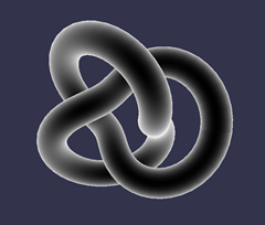
The result looks like a cartoon object:
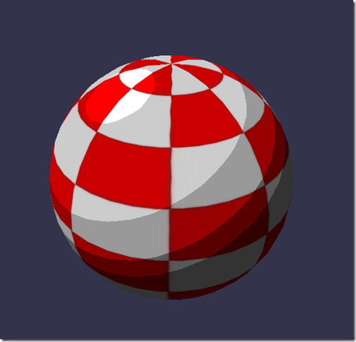
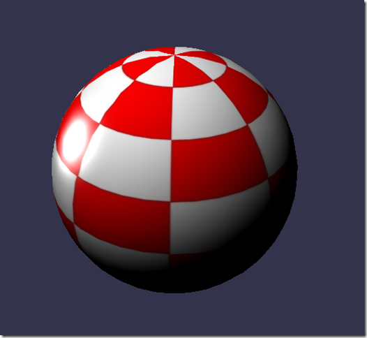
Phong shader
We use a portion of the Phong equation in the previous shader. So let’s try to use it completely now.
The vertex shader is clearly simple here because everything will be done in the pixel shader:
precision highp float;
// Attributes

attribute vec3 position;

attribute vec3 normal;

attribute vec2 uv;
// Uniforms

uniform mat4 worldViewProjection;
// Varying

varying vec3 vPosition;

varying vec3 vNormal;

varying vec2 vUV;
void main(void) {

    vec4 outPosition = worldViewProjection * vec4(position, 1.0);

    gl_Position = outPosition;
    vUV = uv;

    vPosition = position;

    vNormal = normal;

}
According to the equation you must compute diffuse and specular part by using light direction and vertex’s normal:
precision highp float;
precision highp float;
// Varying

varying vec3 vPosition;

varying vec3 vNormal;

varying vec2 vUV;
// Uniforms

uniform mat4 world;
// Refs

uniform vec3 cameraPosition;

uniform sampler2D textureSampler;
void main(void) {

    vec3 vLightPosition = vec3(0, 20, 10);
    // World values

    vec3 vPositionW = vec3(world * vec4(vPosition, 1.0));

    vec3 vNormalW = normalize(vec3(world * vec4(vNormal, 0.0)));

    vec3 viewDirectionW = normalize(cameraPosition - vPositionW);
    // Light

    vec3 lightVectorW = normalize(vLightPosition - vPositionW);

    vec3 color = texture2D(textureSampler, vUV).rgb;
    // diffuse

    float ndl = max(0., dot(vNormalW, lightVectorW));
    // Specular

    vec3 angleW = normalize(viewDirectionW + lightVectorW);

    float specComp = max(0., dot(vNormalW, angleW));

    specComp = pow(specComp, max(1., 64.)) * 2.;
    gl_FragColor = vec4(color * ndl + vec3(specComp), 1.);

}
We already used the diffuse part in the previous shader so here we just need to add the specular part. This picture from Wikipedia article explains well how the shader works:
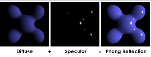
The result on our sphere:
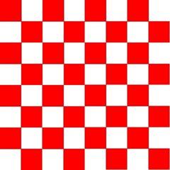
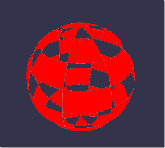
Discard shader
For the Discard shader, I would like to introduce a new concept: the discard keyword.
This shader will discard every non-red pixel and will create the illusion of a dug object.
The vertex shader is the same used by the Basic shader:
precision highp float;
// Attributes

attribute vec3 position;

attribute vec3 normal;

attribute vec2 uv;
// Uniforms

uniform mat4 worldViewProjection;
// Varying

varying vec2 vUV;
void main(void) {

    gl_Position = worldViewProjection * vec4(position, 1.0);
    vUV = uv;

}
The pixel shader on its side will have to test the color and use discard when, for instance, the green component is too high:
precision highp float;
varying vec2 vUV;
// Refs

uniform sampler2D textureSampler;
void main(void) {

    vec3 color = texture2D(textureSampler, vUV).rgb;
    if (color.g > 0.5) {

        discard;

    }
    gl_FragColor = vec4(color, 1.);

}
The result is funny:
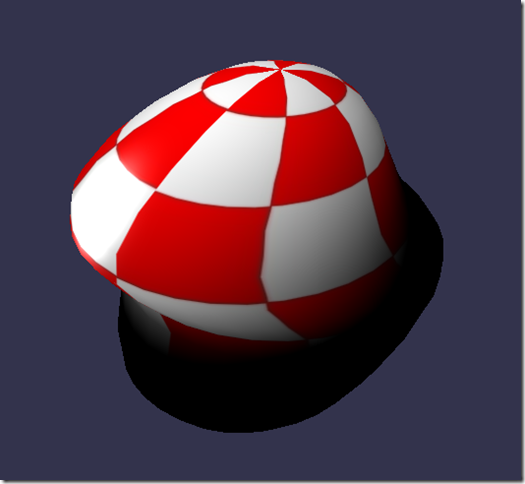
Wave shader
We’ve played a lot with pixel shader, but I also wanted to show you that we can do a lot of things with vertex shaders.
For the Wave shader, we will reuse the Phong pixel shader.
The vertex shader will use the uniform called time to get some animated values. Using this uniform, the shader will generate a wave with the vertices’ positions:
precision highp float;
// Attributes

attribute vec3 position;

attribute vec3 normal;

attribute vec2 uv;
// Uniforms

uniform mat4 worldViewProjection;

uniform float time;
// Varying

varying vec3 vPosition;

varying vec3 vNormal;

varying vec2 vUV;
void main(void) {

    vec3 v = position;

    v.x += sin(2.0 * position.y + (time)) * 0.5;
    gl_Position = worldViewProjection * vec4(v, 1.0);
    vPosition = position;

    vNormal = normal;

    vUV = uv;

}
A sinus is applied to position.y and the result is the following:
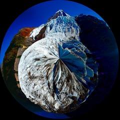
Spherical environment mapping
This one was LARGELY inspired by this tutorial. I’ll let you read that excellent article and play with the associated shader.
Fresnel shader
Finally I would like to finish this article with my favorite: the Fresnel Shader.
This shader is used to apply a different intensity according to the angle between the view direction and the vertex’s normal.
The vertex shader is the same used by the Cell shading shader and we can easily compute the Fresnel term in our pixel shader (because we have the normal and the camera’s position that can be used to evaluate the view direction):
precision highp float;
// Lights

varying vec3 vPositionW;

varying vec3 vNormalW;
// Refs

uniform vec3 cameraPosition;

uniform sampler2D textureSampler;
void main(void) {

    vec3 color = vec3(1., 1., 1.);

    vec3 viewDirectionW = normalize(cameraPosition - vPositionW);
    // Fresnel

    float fresnelTerm = dot(viewDirectionW, vNormalW);

    fresnelTerm = clamp(1.0 - fresnelTerm, 0., 1.);
    gl_FragColor = vec4(color * fresnelTerm, 1.);

}
Your Shader?
You are now more prepared to create your own shader. Feel free to use the comments here or babylon.js forum linked below to share your experiments!
If you want to go further, here are some useful links:
And some more information:
Or, stepping back, our team’s learning series on JavaScript:
- Practical Performance Tips to Make your HTML/JavaScript Faster (a 7-part series from responsive design to casual games to performance optimization)
- The Modern Web Platform JumpStart (the fundamentals of HTML, CSS, and JS)
- Developing Universal Windows App with HTML and JavaScript JumpStart (use the JS you’ve already created to build an app)
And of course, you are always welcome to use some of our free tools in building your next web experience: Visual Studio Community, Azure Trial, and cross-browser testing tools for Mac, Linux, or Windows.
This article is part of the web dev tech series from Microsoft. We’re excited to share Project Spartan and its new rendering engine with you. Get free virtual machines or test remotely on your Mac, iOS, Android, or Windows device at modern.IE.
Frequently Asked Questions about Shaders and WebGL
What is the basic function of a shader in WebGL?
A shader in WebGL is a type of program that is used to perform shading – the process of applying light and color to a 3D object. Shaders are written in a language called GLSL (OpenGL Shading Language) and are executed directly on the GPU (Graphics Processing Unit). They play a crucial role in rendering graphics, as they control the way light interacts with 3D objects, thereby determining the object’s appearance in terms of color, brightness, and texture.
How do shaders differ from other graphic rendering techniques?
Shaders offer a higher level of flexibility and control compared to other rendering techniques. They allow developers to create a wide range of effects by manipulating the attributes of pixels, vertices, and textures. Unlike fixed-function pipeline, shaders are programmable, meaning they can be customized to create unique visual effects.
What are the different types of shaders in WebGL?
There are two main types of shaders in WebGL: vertex shaders and fragment shaders. Vertex shaders process the attributes of individual vertices, such as their position, color, and texture. Fragment shaders, on the other hand, process the attributes of individual pixels, such as their color and depth.
How can I apply a shader to a canvas element?
To apply a shader to a canvas element, you need to create a WebGL context for the canvas, compile the shader code, and then attach the compiled shaders to the WebGL context. This process involves several steps, including creating shader objects, loading shader source code, compiling the shaders, and linking them to a program object.
Can shaders be used in game development?
Yes, shaders are widely used in game development to create realistic lighting effects, simulate water, generate landscapes, and much more. They can greatly enhance the visual appeal of a game and contribute to a more immersive gaming experience.
What is the role of shaders in HTML5?
In HTML5, shaders are used in conjunction with the WebGL API to render complex 3D graphics within a web browser. They allow developers to leverage the power of the GPU to create high-performance, visually stunning web applications.
How can I learn to write shaders?
Learning to write shaders involves understanding the basics of computer graphics, getting familiar with the GLSL language, and practicing writing shader code. There are many online resources, tutorials, and books available that can guide you through this process.
What are the challenges of working with shaders?
Working with shaders can be challenging due to their complexity and the need for a deep understanding of computer graphics. Debugging shader code can also be difficult, as the tools for debugging shaders are not as advanced as those for regular programming languages.
Can shaders improve the performance of my web application?
Yes, by offloading graphics processing tasks to the GPU, shaders can significantly improve the performance of your web application, especially when dealing with complex 3D graphics.
Are there any limitations to using shaders in WebGL?
While shaders offer many benefits, they also have some limitations. For instance, they cannot access the DOM or other web APIs, and they have limited support for data types and functions compared to regular programming languages.