Connecting LIFX Light Bulbs to the IoT Using IFTTT
Key Takeaways
- LIFX smart light bulbs are energy-efficient LED bulbs that can be controlled via smartphones and smartwatches, and can change color based on user preferences.
- The IFTTT (If This Then That) service can be used to set rules for internet-connected devices like LIFX bulbs, triggering responses such as color changes.
- The LIFX bulbs can be set up to turn off when a user’s Jawbone UP24 is in sleep mode, or change color when a favorite sports team is playing, using IFTTT.
- Thanks to services like IFTTT, setting up interactions with internet-enabled devices like LIFX smart light bulbs can be simple and easy for even non-coders.
Have you ever wished your lights would turn off on their own when you went to sleep? Or that they’d change color when your favorite sporting team scored? With LIFX smart light bulbs and IFTTT, we’re pretty close to that ideal and magical connected light bulb reality.
LIFX smart light bulbs are energy efficient LED bulbs that can change color and be controlled via smartphones and smartwatches. They are quite entertaining and rather easy to set up on your home Wi-Fi network.
To give our lights some autonomy, we’ll be using a service called IFTTT (short for “If This Then That”) which allows you to set rules based upon different internet connected devices and/or services. These rules can then trigger responses like your smart light bulbs changing color.
In this article, we’ll explore how to set up a LIFX smart bulb and then we’ll explore connecting it to IFTTT. Within IFTTT, we will set our lights to turn off when our Jawbone UP24 is in sleep mode. Afterwards we will look at how to set the bulb to change color if our favourite sporting team is playing.
Setting Up Our LIFX light bulbs
To get started, you’ll need to ensure your light bulbs are connected to your home network. You’ll need to run the iOS or Android LIFX app to set this up.
I’m on Android, so I’ve installed the LIFX Android app:
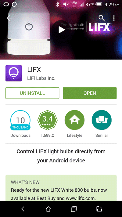
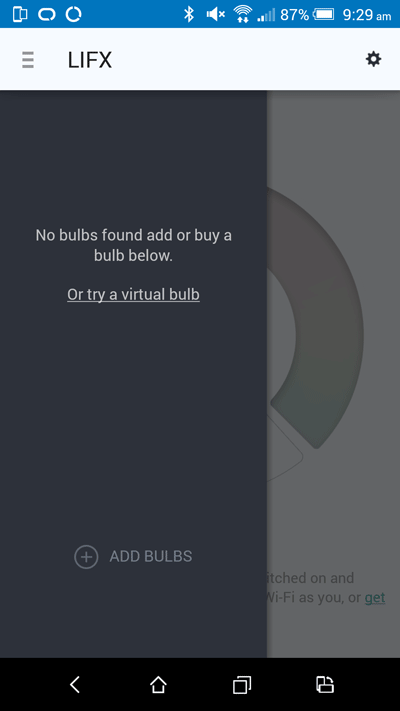
Open the app and click “Add Bulbs” to set up your LIFX light bulb. Make sure your LIFX light bulb is turned on otherwise it may not appear!
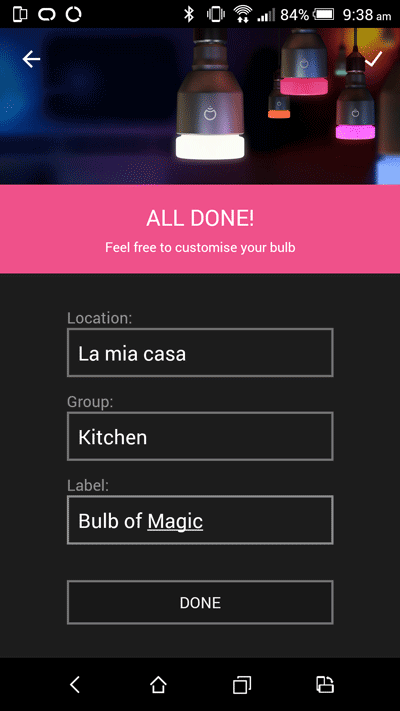
Choose your bulb and your home Wi-Fi connection, then you’ll be greeted with this wonderful screen allowing you to name the location of your LIFX light bulb, assign it to a group and give it a name:
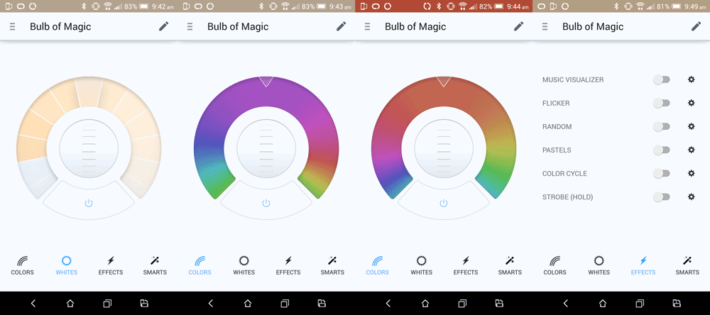
Once it assigns all of those settings, you’ll see your new location and group in the LIFX menu with your bulb inside it. If you press the power button next to the location, group or individual LIFX light bulb, the light will turn off. If it turns off successfully, then you are ready to go!

You can click on the bulb name in the menu to open up the controls for your bulb. Here you can change the color of the light (either different shades of white or completely new colors like purple from the “Colors” button on the bottom left). You can also set up effects like a strobe light via the “Effects” button.
Now you’ve had a bit of fun with those settings, let’s look into how to connect up the LIFX light bulb to other web triggers via IFTTT.
Connecting Our LIFX Light Bulb To IFTTT
To create a new recipe, create an account on IFTTT and log in. Then, click your username in the top right and choose “Create”. This takes you to your New IFTTT Recipe Page.

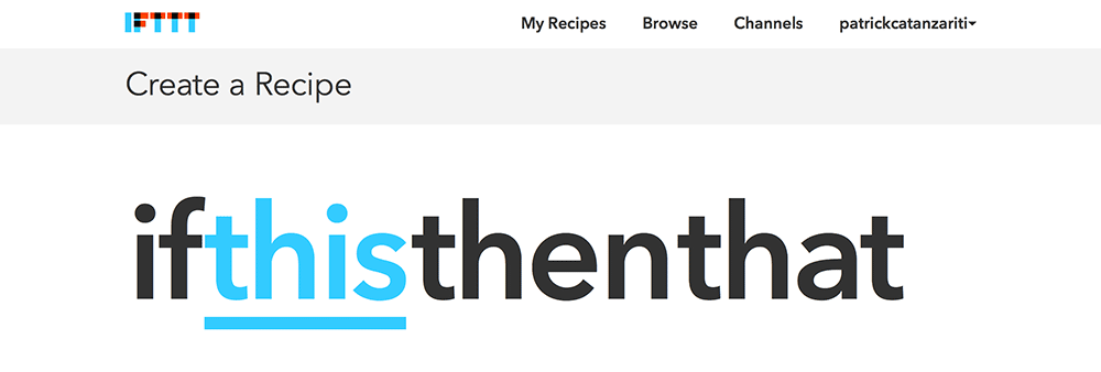
We are then taken to a screen saying “ifthisthenthat”, click the “this” link to begin our process:
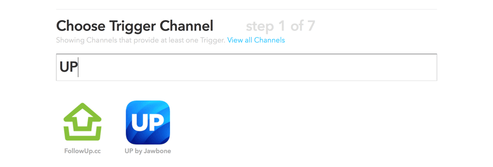
In the “Choose Trigger Channel” section, type in “UP” and choose the UP icon that appears.
If you are new to IFTTT and haven’t previously connected your UP to the service (likely!), there’ll be a screen that shows a button saying “Connect”. Click that button and follow the prompts to give IFTTT permission to access your UP data.
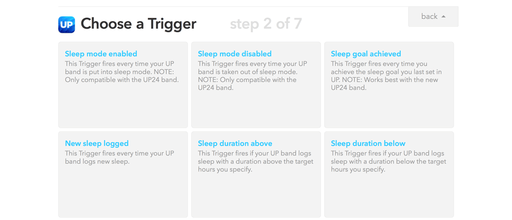
Once you are set up, choose “Sleep mode enabled” in the trigger options that appear.
Finish it by clicking “Create Trigger”.
Now we’ll have “if UP Sleep mode enabled then that” awaiting us. Click “that” to set up our LIFX smart bulb.

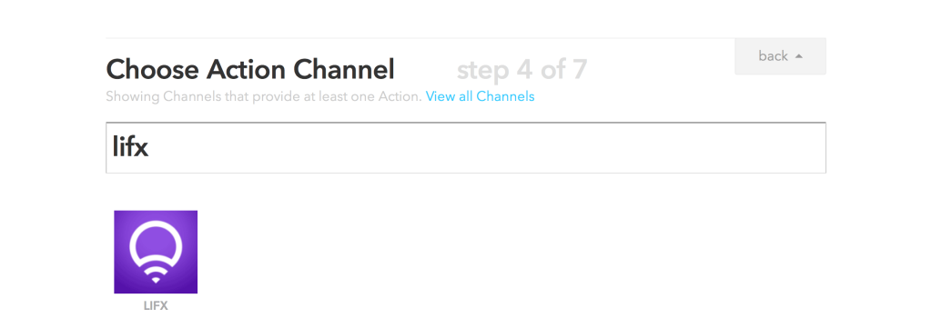
Type in “lifx” into the “Choose Action Channel” filter and click the LIFX icon. You are likely to need to connect up LIFX too, click the “Connect” button and go through the prompts to give IFTTT access to your LIFX account.
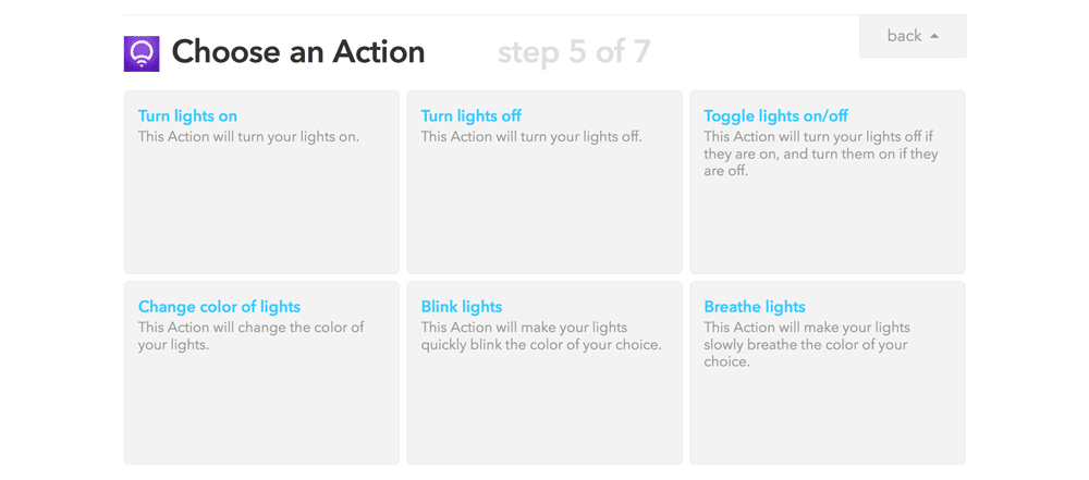
We’ll arrive at the “Choose an Action” section, here we select “Turn lights off”. This will set our light to be off when sleep mode is enabled.
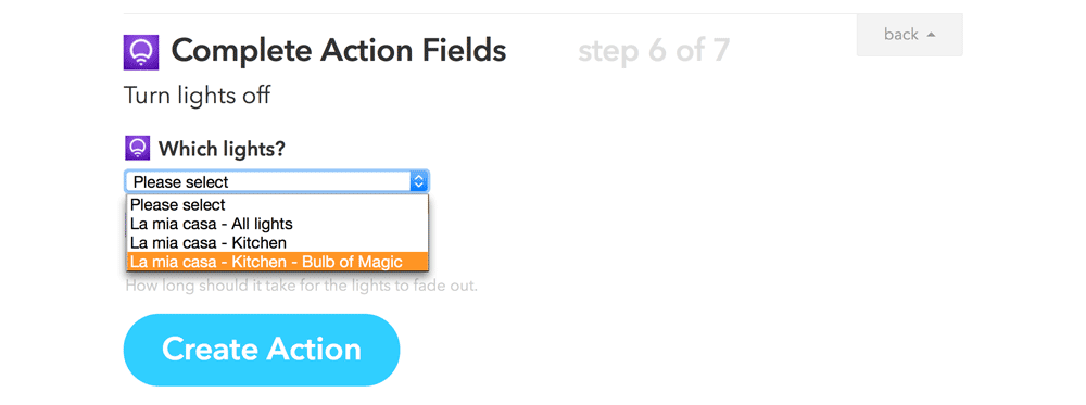
Before IFTTT can turn off our light, it needs to know which lights we’d like to turn off. You can choose individual light bulbs, or whole locations or groups. I chose the individual bulb.
Next, we can set how long we’d like our lights to gently fade to the off state. I’d personally like to get straight to sleep in the wonderous glow of darkness, so I’ve selected “Instant”.
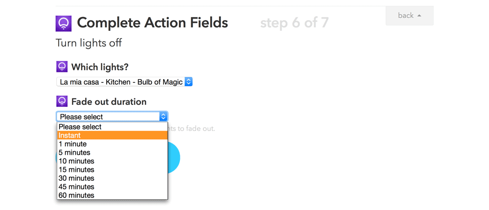
Then click “Create Action” to finish setting up this action.
Now you can give your IFTTT recipe a name and set whether you want your phone to notify you each time it runs. I’d recommend not setting your phone to notify you here as this is something we’d like to happen silently so we can rest! Once you are happy with the name and notification settings, click “Create Recipe”.
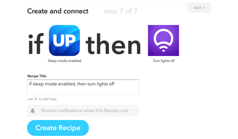
Once it has created your recipe, it will direct you back to your My Recipes page where you’ll see your new recipe ready and waiting to be tried out!
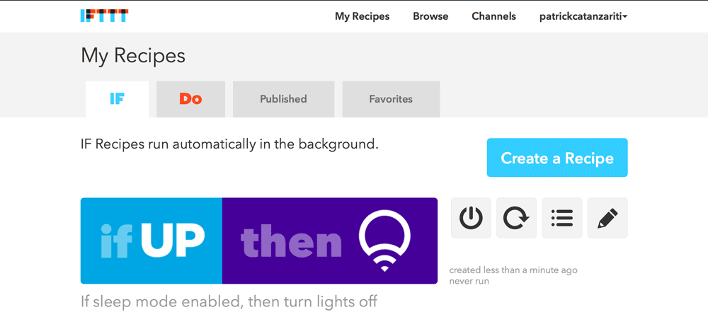
Testing Out Our Connected Light Bulb
Now for the fun part. Get our your Jawbone UP24 and set it to Sleep Mode. Your smart light bulb should automatically switch off!
If you wanted to set the light to turn on again when you wake up, you could set another recipe to do the opposite. For me though, it’s usually daylight outside when I wake up so I’d rather not turn my light on each morning unnecessarily.
Connecting Up Our Light Bulb To ESPN
We can also use IFTTT to change the color of our light bulb depending on different triggers. Let’s explore triggering our light bulb color to change whenever our favourite sporting team is playing!
Go through and create a new recipe as we did before, however this time for the “Choose Trigger Channel” section, find and select ESPN:

On the next screen, choose “New Game Start”:
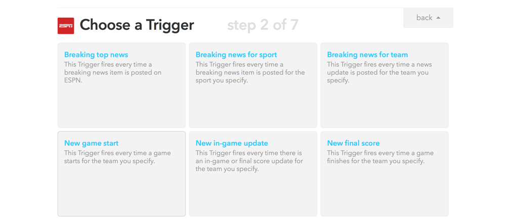
Then choose the sport and team you’d like to trigger the action. I chose my favourite NBA team – the Phoenix Suns.

After that, choose LIFX again as the Action Channel, however rather than turning off our lights, choose “Change color of lights”.

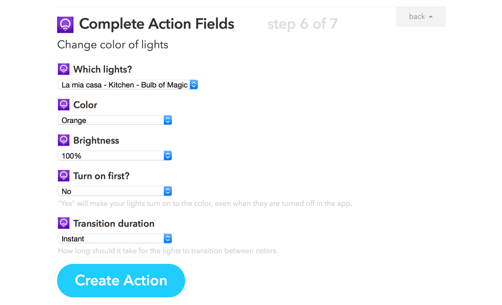
Our options for this one are a lot more plentiful than the turning off light option! Here you can choose what color you’d like the light to change to, choose how bright you’d like it to be (or leave it at the brightness it already is), say whether you’d like this action to turn on the light if it isn’t already switched on (I chose “No” as Phoenix might be playing whilst I’m not home and I’d rather not cause a huge energy bill from an eager Phoenix Suns smart light bulb!) and then finally how long the transition should be (I chose “Instant” once again because I want it to happen straight away). Once you are happy with all those settings, click “Create Action”.
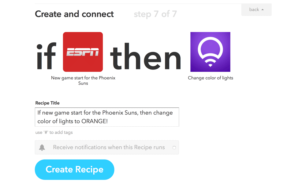
Finish it by clicking “Create Recipe” and surprise your friends when they come over to watch the next sporting match with you!
Conclusion
Not every bit of IoT enabled functionality necessarily needs a truck load of coding! Thanks to services like IFTTT and devices like the LIFX smart light bulb, setting up delightful interactions with internet enabled devices can be simple and easy for even non-coders to complete! Have you got a favourite IoT based IFTTT recipe? Did you come up with a good alternative trigger for your own LIFX smart light bulbs? Leave a note in the comments or get in touch with me on Twitter (@thatpatrickguy), I’d love to hear about it.
Frequently Asked Questions about Connecting LIFX Light Bulbs to IoT using IFTTT
What is the LIFX light bulb and how does it work?
The LIFX light bulb is a smart, Wi-Fi enabled, multi-color, energy-efficient LED light bulb that you can control with your smartphone. It works by connecting to your home’s Wi-Fi network, allowing you to control its settings and features through the LIFX app. You can adjust the brightness, change the color, set schedules, and even sync the light with your music or TV.
How do I connect my LIFX light bulb to the Internet of Things (IoT)?
To connect your LIFX light bulb to the IoT, you need to first ensure that the bulb is properly installed and connected to your home’s Wi-Fi network. Once that’s done, you can use the LIFX app to control the bulb and connect it to other smart devices in your home. You can also use platforms like IFTTT (If This Then That) to create automated actions between your LIFX bulb and other IoT devices.
What is IFTTT and how does it work with LIFX light bulbs?
IFTTT is a free web-based service that allows you to create chains of simple conditional statements, called “applets”. These applets are used to automate certain actions between various internet-connected devices and services. When it comes to LIFX light bulbs, you can use IFTTT to create applets that control your lights based on certain conditions. For example, you can create an applet that turns your LIFX lights on at sunset each day.
Can I control multiple LIFX light bulbs at once?
Yes, you can control multiple LIFX light bulbs at once using the LIFX app. You can group bulbs together and control them as a unit, allowing you to adjust the brightness or color of all the bulbs in the group at the same time. This is particularly useful if you have multiple LIFX bulbs in one room or area of your home.
How do I set up schedules for my LIFX light bulbs?
Setting up schedules for your LIFX light bulbs is easy with the LIFX app. You can create schedules that turn your lights on or off at specific times, change the color or brightness of your lights at certain times, or even sync your lights with your daily routine. To set up a schedule, simply open the LIFX app, select the bulb or group you want to schedule, and then choose the “Schedule” option.
Can I use LIFX light bulbs outdoors?
LIFX does offer certain light bulbs that are designed for outdoor use. These bulbs are weatherproof and designed to withstand the elements, making them a great choice for outdoor lighting. However, not all LIFX bulbs are suitable for outdoor use, so it’s important to check the specifications of the bulb before installing it outdoors.
Do LIFX light bulbs work with other smart home systems?
Yes, LIFX light bulbs are compatible with a variety of smart home systems, including Amazon Alexa, Google Home, and Apple HomeKit. This means you can control your LIFX lights with your voice using these systems, or integrate them into your existing smart home setup.
How energy efficient are LIFX light bulbs?
LIFX light bulbs are very energy efficient. They use LED technology, which consumes significantly less energy than traditional incandescent or halogen bulbs. Additionally, because they’re smart bulbs, you can control them remotely and set schedules to ensure they’re only on when needed, further saving energy.
What is the lifespan of a LIFX light bulb?
The lifespan of a LIFX light bulb is approximately 22.8 years based on three hours of use per day. This makes them a long-lasting and cost-effective lighting solution.
Can I use LIFX light bulbs even if I don’t have a smart home system?
Yes, you can use LIFX light bulbs even if you don’t have a smart home system. All you need is a Wi-Fi connection and the LIFX app on your smartphone. This allows you to control the bulb’s settings and features directly from your phone, no smart home system required.
PatCat is the founder of Dev Diner, a site that explores developing for emerging tech such as virtual and augmented reality, the Internet of Things, artificial intelligence and wearables. He is a SitePoint contributing editor for emerging tech, an instructor at SitePoint Premium and O'Reilly, a Meta Pioneer and freelance developer who loves every opportunity to tinker with something new in a tech demo.


