In this tutorial, we’ll look at a technique for using CSS and JavaScript to build a first-person-perspective maze, in homage to old-school adventure games like Dungeon Master and Doom.
In truth, the scripting involved is fairly complex, and it won’t be possible for me to spell out every nuance of the code in this single tutorial. In fact, I won’t even list every method used in the script, as some of them are quite long. What I can do, though, is introduce you to the principles of creating shapes and perspective with CSS, and the task of using JavaScript to generate those shapes on demand to create a dynamic, three-dimensional perspective from a static, two-dimensional map.
The script, and all of its components, are included in the tutorial’s downloadable code archive. All the code is robustly commented, so you should find it easy to follow. I recommend that you have it available to view as you read, so that you can refer to it as we go along.
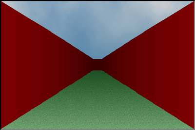
Before we dive into a discussion of how it’s built, let’s take a look at the final result — it’s shown below.
That screenshot was taken with Opera, in which this script was originally developed, and it also works as intended in Firefox, Safari, and Internet Explorer 7. IE 6, however, is not fully supported: the game works, but it looks poor because IE 6 doesn’t have all the CSS support we need (most notably, it lacks support for transparent borders). This tutorial was developed for SitePoint’s book The Art & Science of JavaScript, and you can download it to keep and read offline. That downloadable PDF also includes the chapter on tables, in which I guarantee you’ll find a few surprises!
I should also point out, in case it crosses your mind, that what we’re doing here has no practical use. In fact, it could be argued that we’re not really using the right technology for the job. I made this maze because I wanted to see if it was possible — to push the envelope a little in terms of what can be done with JavaScript and CSS. But we’re right at the edge of what’s reasonable, and maybe Flash or SVG would be better suited to building a game like this.
But hey — why climb a mountain? Because it’s there!
Key Takeaways
- Utilize CSS and JavaScript to create a first-person-perspective maze, drawing inspiration from classic adventure games.
- Explore the complexity of scripting for dynamic shape generation and the limitations of CSS in older browsers like IE 6.
- Learn about the innovative use of CSS to create right-angle triangles and polygons, crucial for the maze’s 3D perspective.
- Understand the floor plan’s role in defining the maze structure and how JavaScript translates this into a navigable 3D space.
- Recognize the non-practical, experimental nature of the project aimed at pushing the boundaries of what can be achieved with JavaScript and CSS.
- Examine the downloadable code which includes detailed comments to aid understanding and modification of the maze script.
- Delve into the potential for further development, including multiplayer capabilities and enhanced interactivity using Ajax and server-side programming.
Basic Principles
In 2001, Tantek Çelik published a technique for creating shapes using the interactions between CSS borders. We’re going to use that technique to make a bunch of right-angle triangles.
Why triangles, I hear you ask? Well, because once you can render a triangle, you can render any polygon that you like. By combining triangles with the rectangles that we’ve always been able to render (using a good old div and the background-color property), we can create the walls of our maze and contribute to the sense of perspective. As you’ll see, we’ll draw these walls by slicing the player’s view up into a number of columns.
We’ll also need a floor plan for our maze, and a handful of methods for dynamically converting that floor plan into the polygons that represent the walls of our maze.
Making Triangles
If an element has a very thick border (say 50px), and adjacent borders have different colors, the intersection of those borders creates a diagonal line, as the figure below illustrates.
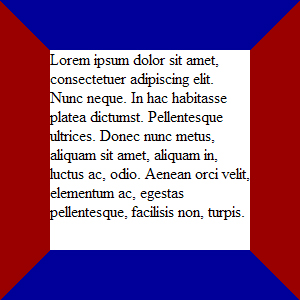
That example is simply a div element to which the following CSS rules are applied:
width: 200px;
height: 200px;
border: 50px solid #900;
border-color: #009 #900;
To render a triangle, we don’t actually need the contents of that div — we only need its borders. So let’s remove the text, and reduce the width and height values to zero. What we’re left with is the image shown below.
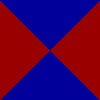
Here’s the CSS that achieves that effect:
width: 0;
border: 50px solid #900;
border-color: #009 #900;
If we were to vary the relative border widths (applying, say, 50px on the left border and 25px on the top), we could create triangles with various angles. By setting the color of one of the borders to transparent, the diagonal line from the solid border stands alone, as the figure below reveals.

Now, if we wrap a second div element around the first, we’ll be able to extract a single, discreet triangle. We can achieve this by:
-
- applying position: relative to the outer container
-
- applying position: absolute to the inner element
- clipping the inner element
Clipped elements are required to have absolute positioning, so the relative positioning on the container provides a positioning context for the inner element, as the figure below shows.
![]()
The code that produces that figure is still very simple. Here’s the HTML:
<div id="triangle">
<div></div>
</div>
And here’s the CSS:
#triangle
{
  border: 2px solid #999;
  position: relative;
  width: 50px;
  height: 25px;
}
#triangle > div
{
  border-style: solid;
  border-color: transparent #900;
  border-width: 25px 50px;
  position: absolute;
  left: 0;
  top: 0;
  clip: rect(0, 50px, 25px 0);
}
Clipping and positioning is the crux of our ability to create discreet shapes using CSS. If we removed the clip, we’d get the result shown below.

You can see that by varying the clip and position properties on the inner element, we control which part of it is shown, and hence which of the triangles will be visible. If we wanted the bottom-right triangle, we would apply these values:
left: -50px;
top: -25px;
clip: rect(25px, 100px, 50px, 50px);
And we’d get the result depicted here.
![]()
Defining the Floor Plan
The essence of our maze script lies in our ability to create a three-dimensional perspective from a two-dimensional map. But before we can make sense of how the perspective works, we must look at the map — or, as I’ll refer to it from now on, the floor plan.
The floor plan is a matrix that defines a grid with rows and columns. Each square in the floor plan contains a four-digit value that describes the space around that square — whether it has a wall or floor on each of its four sides. As we’ll see in a moment, we’ll use a 1 or a 0 for each of the four digits.
Understanding clip
clip totally confuses me — every time I use it, I have to think about how it works all over again. To help jog your memory, the figure below illustrates what the values in that clipping rectangle mean.
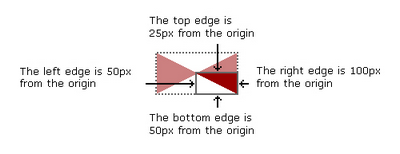
The main element in this example (indicated by the dotted line) is 100px wide and 50px high. The four values in the clipping rectangle are (in order): top offset, right offset, bottom offset, and left offset. Each of these values defines the offset of that edge from the main element’s origin (its top-left corner).
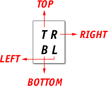
These values are specified in the same order (top, right, bottom, left) as they are for other CSS properties, such as border, padding, and margin. Thinking of the word trouble (TRBL) should help you remember the correct order.
The figure below shows how each of these squares is constructed.
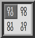
The figure below shows a simple floor plan that uses four of these squares.
In the image above:
- A dark gray block represents a square of solid wall.
- The borders at the edge of the diagram also represent solid wall.
- A light gray block represents a square of open floor.
For each square in the diagram:
- The digit
0means “there’s solid wall in this direction.” Think of the number0as being shaped like a big brick, which means “Nope, you can’t walk here.” - The digit
1means “there’s open floor space in this direction.” Think of the number1, being a positive value, as “Yes, you may walk on this square.” - Each of the four digits in a square represents a direction when the floor plan is viewed from above. The numbers should be read left-to-right, top-to-bottom, and they should appear in the same clockwise order as CSS values: top, right, bottom, left (or, when considered from the point of view of someone within the maze: forward, right, backwards, left).
A square like the one in the top-right of the image above therefore represents the following information:
- The four-digit number represented is
0010. - There are solid walls above, to the right, and to the left of the square.
- There is open floor space below the square.
As you can see, the concept is rather similar to the classic Windows game, Minesweeper!
The floor plan in the figure above would be represented in JavaScript by the following matrix:
this.floorplan = [['0110','0010'], ['0100','1001']];Note that these values are strings, not numbers; with numbers, leading zeros are not preserved, but in this case those leading zeros are an important part of the data.
So far, we’ve only seen very small examples of floor plan data. To make our maze really useful, we’ll want something much larger — the floor plan included in the code archive is 20 by 40 squares, and even that is comparatively small.
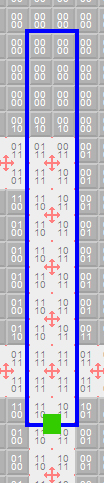
Just for kicks, the figure below shows what that floor plan looks like — you can refer to this plan if you get lost wandering around! As before, the light squares represent floor space and the dark squares depict solid wall, while the red cross-marks show positions where the person navigating our maze (from here on referred to as the player) can stand.
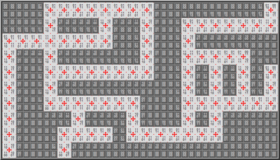
I don’t expect you to be able to read those numbers! But later on, when we talk about the floor plan designer that goes with the game, you can look at this plan in its original context. The floor plan designer is also included in the code archive.
There are Many Ways to Skin a Cat!
There are, of course, numerous ways to approach a problem like this, each with its own pros and cons. For example, instead of binary digits, we could have used letters like WFFW to indicate wall and floor space. We could have made use of nested arrays, like [[[0,1,1,0],[0,0,1,0]]]. We could even have represented each square using only a single digit, which would certainly have made creating and modifying a floor plan easier.
The reason I chose to use four digits is because, this way, each square is able to represent what’s around it, rather than what the square itself is. If we had a floor plan that used single digits, and we wanted to represent the view from the middle square, we’d need not only that square’s data, but also the data from the four squares that surrounded it.
With the approach I’ve taken, we only need the data from the middle square to know what those surrounding squares are. Granted, we end up with some duplicate data in our floor plan. However, in terms of pure computational efficiency, the two are equivalent, and using four digits makes more sense to me as each square is much more self-contained.
Creating Perspective
Now that we understand how the floor plan works, and we’ve seen how to make triangles, we have all the data — and the building blocks — we need to create a 3D view.
Take a look at the figure below. What this diagram shows is a breakdown of all of the elements that create the illusion of perspective in our maze. The walls on each side of the long hallway are composed of 16 columns. Each of the columns contains four inner elements which, for the rest of this chapter, we’ll refer to as bricks. I’ve labeled the bricks, and highlighted them in a different color so that they’re easier to distinguish. In each column, the top brick is highlighted as a gray rectangle; the upper brick is a rectangle comprising a red and blue triangle, as is the lower brick; and the middle brick is a green rectangle.
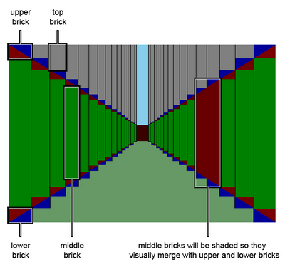
The upper and lower bricks are implementations of the triangles we saw earlier, clipped differently for each of the four orientations we need, thus creating diagonal lines in four directions. The red parts of these bricks will always be visible, whereas the blue parts are only blue for demonstration purposes — in practice, they’ll be transparent. The top bricks will also be transparent, to expose a sky-patterned background. (It isn’t strictly necessary to use top bricks — we could have applied a top margin to the upper bricks — however, it was easier for me to visualize this way.) The middle bricks will be shaded the same dark red color as the triangles in the upper and lower bricks, so that the bricks merge together and create the appearance of part of a wall.
This Is Not a True Perspective!
What we’re dealing with here is not actually a true perspective — it’s skewed slightly so that the vanishing point is a short vertical line, rather than a point.
I originally created this maze using a true perspective with a single vanishing point, but it just didn’t look right. The ceiling appeared too low relative to the distance between the walls (or the walls were too far apart, depending on how you looked at it). Changing the aspect ratio (that is, making the viewport square instead of the widescreen ratio that it has) would have made a difference, but I didn’t want to do that — I wanted the game to look more cinematic!
The view is also limited as the columns get smaller, rather than stretching all the way to the vanishing point, because the resolution that we can achieve at such a distance is limited. The view ends at the point where we no longer have enough pixels to draw effectively, which restricts the maximum length of corridor we can represent. We’ll talk about this issue again, along with the other limitations of this approach, towards the end of the chapter.
If you look carefully, you’ll see in the figure above that each of the triangles has the same angle — it’s just the size of the brick itself that’s progressively reducing. This makes the illusion of perspective nice and easy to create, as we don’t have any complex math to worry about. Still, it’s not something that we’d want to code by hand. Let’s use JavaScript to calculate the size of each brick, so that it can be generated on the fly …
Making a Dynamic View
One of the beautiful things about using a programming language to generate complex visual patterns is that it’s not necessary for us to work out every line and angle manually — we only need to worry about the math that represents the pattern.
There are times when I really wish I’d paid more attention in school math classes. But computer games were in their infancy then, and none of my teachers knew much, if anything, about them. So when I asked in class, “What use is any of this?”, they didn’t have a good answer!
It’s just as well, then, that the math involved here is not complicated — we don’t even need trigonometry, because the angles have already been determined for us. All we need to calculate is the size of the bricks and the clipping regions that are used to create our triangles; the browser’s rendering engine will do the rest.
Core Methods
Let’s take a look at the scripting now. We’ll start with the main script, underground.js, which is located in the scripts folder of the code archive. The entire script would be too large to list in its entirety in this book; instead I’ve just listed the signature of each method to give you a high-level appreciation for what’s going on:
Example 6.1. underground.js (excerpt)

// DungeonView object constructor
function DungeonView(floorplan, start, lang, viewcallback)
{ ... };

// Create the dungeon view.
DungeonView.prototype.createDungeonView = function()
{ ... };

// Reset the dungeon view by applying all of the necessary
// default style properties.
DungeonView.prototype.resetDungeonView = function()
{ ... };

// Apply a floorplan view to the dungeon
// from a given x,y coordinate and view direction.
DungeonView.prototype.applyDungeonView = function(x, y, dir)
{ ... };

// Create the map view.
DungeonView.prototype.createMapView = function()
{ ... };

// Reset the map view.
DungeonView.prototype.resetMapView = function()
{ ... };

// Apply a position to the map view.
DungeonView.prototype.applyMapView = function()
{ ... };

// Clear the view caption.
DungeonView.prototype.clearViewCaption = function()
{ ... };

// Generate the caption for a view.
DungeonView.prototype.generateViewCaption = function(end)
{ ... };

// Shift the characters in a string by n characters to the left,
// carrying over residual characters to the end,
// so shiftCharacters('test', 2) becomes 'stte'
DungeonView.prototype.shiftCharacters = function(str, shift)
{ ... };

// Bind events to the controller form.
DungeonView.prototype.bindControllerEvents = function()
{ ... };
Rather than examine every method here, I’ll explain the three core methods that do most of the work for our script, and leave you to fill in the gaps by following the code from the code archive yourself. Throughout this section I’ll use the word view to mean “a 3D representation of a position on the floor plan” (that is, the player’s point of view, looking north, east, south, or west).
The createDungeonView Method
The createDungeonView method takes an empty container, populates it with all the elements we need (the columns are divs, and the bricks are nested spans), and saves a matrix of references to those elements for later use:
Example 6.2. underground.js (excerpt)

// Create the dungeon view.
DungeonView.prototype.createDungeonView = function()
{
  var strip = this.tools.createElement('div',
                  { 'class' : 'column C' }
              );
  this.grid['C'] = this.dungeon.appendChild(strip);

  for(var k=0; k<2; k++)
  {
    // the column classid direction token is "L" or "R"
    var classid = k == 0 ? 'L' : 'R';
    for(var i=0; i<this.config.gridsize[0]; i++)
    {
      var div = this.tools.createElement('div',
          { 'class' : 'column ' + classid + ' ' + classid + i }
      );
      this.grid[classid + i] = {
          'column' : this.dungeon.appendChild(div)
      };
      for(var j=0; j<this.config.gridsize[1]; j++)
      {
        // create the main span
        var span = this.tools.createElement('span',
            { 'class' : 'brick ' + this.bricknames[j] }
        );
        if (j == 1 || j == 3)
        {
          var innerspan =
              span.appendChild(this.tools.createElement('span'));
        }
        this.grid[classid + i][this.bricknames[j]] =
            div.appendChild(span);
      }
    }
  }
  this.resetDungeonView();
};
As you can see if you scroll through the code, there isn’t much more to this method: its sole responsibility is to create a group of elements, and assign class names to each of them so that they can be distinguished from one another. The values I’ve used are reasonably intuitive — upper identifies an upper brick, for example.
I’ve made use of CSS floats in order to line the columns up (left floats for a column on the left wall, and right floats for one on the right). To create the columns, we iterate on each side from the edge inwards (in other words, the left-most column is the first of the columns that comprise the left wall, and the right-most column is the first for the right wall).
The resetDungeonView Method
The resetDungeonView method applies style properties (size, position, clip, background, and border-color) to the elements that form the most basic view — that shown when our user is looking straight down a corridor that stretches the maximum distance that our script can support, as depicted in the figure below.
This method can be called whenever we need to reset the view, which we’ll do at initialization, and again before applying each new view. It works by iterating through the matrix of element references we created in createDungeonView; it calculates the width of each column and the height of each of the bricks inside it.
To perform this calculation, we need to define some structural constants. These constants can be found in the configuration script, config.js, which is also in the code archive’s scripts directory:
Example 6.3. config.js (excerpt)
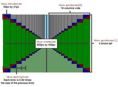
this.viewsize = [600, 400]; // [1]
this.gridsize = [16, 4]; // [2]
this.bricksize = [50, 31]; // [3]
this.multiplier = 0.84; // [4]These constants represent the following values:
-
- The viewsize represents the total width and height of the view container.
-
- The gridsize represents the number of columns from the edge of the viewsize to the center, and the number of bricks from top to bottom.
-
- The bricksize is the size of the upper and lower (triangle-creating) bricks.
- Finally, the multiplier controls the factor by which the brick size is reduced for each column as we move towards the center of the view.
The figure below shows the same perspective diagram that we saw in the previous figure, this time with captions indicating how each of these structural constants applies.
Working Out the Values
I’d love to say I had a clever mathematical algorithm for calculating the values I’ve used here (and there probably is one), but I can’t. I just used trial and error until I arrived at something that looked about right. Note, however, that the values are very closely interrelated, so be extremely careful when adjusting them!
The choice of correct values is also dependent upon the overall performance of the script — it would be possible to create a higher resolution maze with a larger number of smaller bricks. However, that would mean we had more objects to render, which would result in lower overall performance. Even with the default values that I’ve set above, you need a fairly decent computer to render this maze effectively.
If you have a look at the above figure, you’ll notice that the bricks line up perfectly — in each column, the upper brick is exactly below and to the side of the upper brick in the previous column; likewise, each lower brick lines up below and to the side of its neighbor. The clip and position values of the inner elements of those bricks decrease proportionally as the brick size decreases, while the height of the top and middle bricks changes as necessary to complete the wall.
Finally, in order to improve the appearance of perspective, we want each column to be slightly darker than the previous one. To achieve that goal, I’ve introduced constants that define the base color of our bricks and the darkening proportion that’s applied to them. We’ll define the wallcolor using RGB values — they’re easier to work with, as the values are decimal rather than hexadecimal. We’ll name the constant that controls the darkness of each column the darkener. Both of these constants are defined in the config.js file:
this.wallcolor = [127, 0, 0];
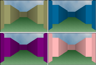
this.darkener = 0.95;On each iteration of our code, we render a single column on each side, moving towards the center of the view; the base color is darkened by the amount specified in the darkener constant. I chose a dark red for the main demo (dark colors generally work best), but as the next figure shows, you can use any color you like — even pink!
The applyDungeonView Method
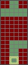
The applyDungeonView method applies style variations to the basic view, creating passageways off to either side of our main passage. To do this, it first compiles a matrix, stored in the variable this.squares, which is a subset of the complete floor plan. This matrix consists of only those floor plan squares that are necessary for us to render the player’s view from the current location in the maze.
The figure below shows an excerpt of a floor plan. The green square highlights the spot where the player is currently standing, while the blue border surrounds what the player can see. It’s the region inside this blue border that defines the part of the plan required to draw the view for the player.
In this example we’re looking north, and each of the floor squares provides us with information about the surrounding squares. However, for any direction of movement, the player is always looking “forwards,” and it’s the player’s view that we render. So the first thing we must do is translate the data contained within each square into data that’s accurate for the direction in which the player is facing. Let me explain this with an example …
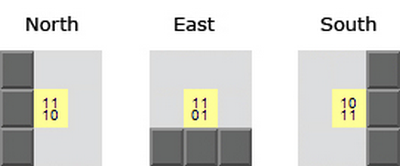
Remember that the digits in a square indicate the presence of wall or floor surrounding that square, in clockwise order, starting from the top. Well, we want those four digits always to indicate that information clockwise from the top, regardless of the direction in which the player is actually facing. Should we have the value 1110 when facing north, then, when the player was facing east, that same square would be represented by the value 1101. When the player faced south, the value would be 1011, as shown here.
So, as we compile the this.squares matrix, we need to translate each square’s value to the direction in which the player is facing. A small utility method named shiftCharacters performs this translation: str is the four-digit string, and shift is the number of times the square must be rotated in a counterclockwise manner when the player turns in a clockwise direction. Each turn corresponds to each of the four digits that represent that square moving to the left by one position (with the left-most digit jumping to the end of the string).
To continue with the example in the figure above, if the player’s view was to change from north (with floor plan data of 1110) to west (0111), the shift value would be 3.
The shiftCharacters method looks like this:
Example 6.4. underground.js (excerpt)

DungeonView.prototype.shiftCharacters = function(str, shift)
{
  var saved = str.substr(0, shift);
  str = str.substring(shift);
  str += saved;
  return str;
};
Once we have the data we need, we can iterate through it and create the actual view. This is where things get rather tricky.
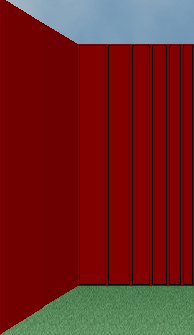
First of all, we need to iterate forwards through the squares, starting from the player’s current location. With each iteration, we test the first digit of each square (which tells us what’s in front of it) until we find the end wall. The end wall marks the limit of what the player can see — every column from that point onwards should be assigned the same height and color. These columns will create the illusion of a facing wall, as shown in the figure below.
Once we know the limit of the player’s view, we iterate from that point backwards through the floor plan data towards the player’s location, looking for adjoining passageways. We need to iterate backwards because the height of a passageway’s facing wall is the height of the furthest column that defines it.
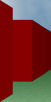
To illustrate, the figure below shows another excerpt from the perspective diagram, this time with lines and shading overlaid to show a corridor with a passageway off to the left.
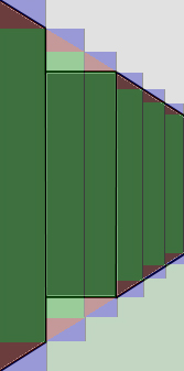
If we want those second and third columns to create that passage to the left, we need to remove the upper and lower bricks from those columns, leaving only the middle bricks, which then must be resized as necessary. But our passage is two columns across, and it’s the furthest column (or what we might call the corner column) that determines the height of the wall — not the nearest. So we need to modify that corner column first, so that we know how tall to make the adjacent columns.
Iterating forwards would require us to jump two steps ahead to find the corner, then move one square back to make a further adjustment. And that’s why we iterate backwards, rather than forwards. (I told you it was tricky!)
When we create those passageways, we also lighten the facing walls slightly, to improve the visual appearance and make the wall look more realistic. As we did when we darkened the walls, we use a single constant value (I’ve called it the lightener) to determine the amount of lightening required:
this.lightener = 1.25;As with the height value, the lightening is applied to the corner column first, then copied onto the nearer column (for the same reasons). And once again, as with all of the constants used in this script, I have no magic formula to share for how these values were obtained?they’re just what looked right after trial and error.
The figure below shows the same view excerpt again — this time without the exposed construction — looking as it does in the final game.
Applying the Finishing Touches
Now, I hope, you should have a fairly concrete sense of how the script generates perspective views, with walls and passages created as necessary. From the diagrams we’ve seen so far, you can understand that any given view is simply a combination of rectangles and triangles.
One final touch we’ll need to make is to shift the entire view up inside the container in order to raise the horizon slightly. This is just another visual tweak that I included because I think it produces a better-looking and more realistic result, as the figure below shows.

You’ll notice I’ve used images for the sky and floor patterns. These images provide some texture to add to the realism of my maze; they also contain a slight gradient, growing darker as they approach the horizon, which again reinforces the sense of perspective.
The end result is not perfect, though: unavoidable rounding errors occur in the final output figures, and these errors give rise to an occasional discrepancy of one or two pixels between adjacent columns. The shading computation is not exact either — sometimes, on close walls, you can see a slight color difference between two columns that should be exactly the same.
All things considered, however, what we’ve created here is a reasonably convincing 3D maze.
Limitations of This Approach
The approach we’ve taken to build this maze imposes some limitations on the design of a maze floor plan, thus restricting the kind of layout we can draw:
- Corridors must always be two squares wide — we can’t create wider spaces because we don’t have the pieces with which to draw them.
- No single corridor can be longer than 16 squares, as this is the maximum number of pairs of columns that we can draw.
- Walls must also consist of an even number of squares — every block must comprise a block of at least two squares by two squares.
It may help to think of four squares on the floor plan as one single square; those smaller squares only exist so that we have more elements to apply progressive shading to, and hence achieve a better-looking and more realistic 3D view.
Creating the Map View
To the right of the maze view, we’ll add a map that shows the floor plan in the player’s immediate location. I originally added this feature to display a top-down view of the same view that the player can actually see … but then I realized — what’s the point of such a map, if it provides no extra advantage?
Instead, we’ll add a map that shows a little more of the surrounding area, as an aid to orientation. In the view shown below, you can see that the player can only move a short distance forwards before reaching a wall, but the map to the right shows further corridors beyond that wall.
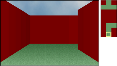
The construction of the map itself is very simple — it’s just a bunch of spans floated in a container. I’ve applied a solid background where there’s wall, and transparency where there’s floor. This allows the green background of the container to show through, as the figure below reveals.
Generating the map is equally simple, since it’s just a two-dimensional representation of data that is itself a 2D matrix.
Remember that when we generated the maze view, we created a matrix called this.squares. This matrix contained as much of the floor plan as was required to generate the current view, with the data transposed so that it represented a forwards view for the player. Well, we can use that same data matrix to generate this 2D map.
To create the map, we begin by coloring every square (using the base wallcolor property). Then we iterate through the matrix of squares, and apply transparency to every square in the map that represents open floor space — including the space directly beneath the spot where the player is standing. The applyMapView method in the file underground.js takes care of this for us:
Example 6.5. underground.js (excerpt)

DungeonView.prototype.applyMapView = function()
{
  this.resetMapView();
  for(var i=0; i<this.squares.L.length; i++)
  {
    var n = this.mapsquares.length - 2 - i;
    if(this.mapsquares[n])
    {
      if(this.squares.L[i].charAt(3) == '1')
      {
        this.mapsquares[n][0].style.background = 'transparent';
        this.mapsquares[n][1].style.background = 'transparent';
        if(i == 0)
        {
          this.mapsquares[n+1][0].style.background = 'transparent';
          this.mapsquares[n+1][1].style.background = 'transparent';
        }
      }

      if(this.squares.R[i].charAt(1) == '1')
      {
        this.mapsquares[n][4].style.background = 'transparent';
        this.mapsquares[n][5].style.background = 'transparent';
        if(i == 0)
        {
          this.mapsquares[n+1][4].style.background = 'transparent';
          this.mapsquares[n+1][5].style.background = 'transparent';
        }
      }

      if(this.squares.L[i].charAt(1) == '1')
      {
        this.mapsquares[n][2].style.background = 'transparent';
        this.mapsquares[n][3].style.background = 'transparent';
        if(i == 0)
        {
          this.mapsquares[n+1][2].style.background = 'transparent';
          this.mapsquares[n+1][3].style.background = 'transparent';
        }
      }
    }
  }
};
Adding Captions
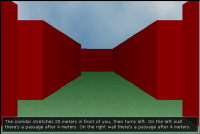
One of the things that excites me most about web programming is its potential for improving accessibility. Although we’re making a visual game here, we have data in a format that can easily be translated into other kinds of output, such as plain text. We can use the same information that we used for making the map to generate a live text description of each maze view, of the kind shown in the figure below.
![]()
Not only does captioning potentially aid comprehension for players who have a cognitive or visual disability, it also extends the basic game play to people who are completely blind — suddenly we can navigate around the maze without any visuals at all! Admittedly, and unfortunately, the game will be much harder to play like this — not just because you have to hold orientation information in your head, but because you don’t have the map to refer to in order to gain clues about what’s behind the next wall.
Still, it’s a start. Try viewing the game with CSS disabled, and you’ll get a basic sense of the experience of what it would be like to play the game if you were blind. I’ve also confirmed that the game is playable in the JAWS 8 screen reader.
Generating the core data for the captions is straightforward?we simply need to know how many passageways there are to the left and right, and how far away they are. We can work this out by:
- iterating once again through the
this.squaresmatrix - building arrays to store the index of each opening
These openings will be converted to a perceived distance. As we navigate our maze, one square looks to be roughly two meters in length, so we’ll adopt this as the scale for our map. We can stop iterating once we reach the end of the player’s view — we’ve created an end variable in the applyDungeonView method, which is the index of this.squares at the point that the view ends. Therefore, we can simply pass this value to the generateViewCaption method when we call it.
In the code, I’ve used len to represent the total length of the corridor in front, and arrays called passages.left and passages.right to store the distance of each passage from the player. The result of our iterations might produce data like this:
var len = 16;
var passages = {
  'left' : [8, 16],
  'right' : [4]
};
This looks simple enough to interpret, right? Well, yes … however, turning this data structure into coherent English is still a little tricky. The basic conversion is easy. Using the data we have, we can describe the view in coarse terms:
“The corridor stretches 16 meters in front of you. To the left there are passages after 8 meters and 16 meters. To the right there are passages after 4 meters.”
However, this language is fairly obtuse. For one thing, we wouldn’t want to say “there are passages” if there was only one. Instead, we’d want to say “there’s a passage.” Additionally, the last passage to the left is at the far end, so it would be nicer to describe that by saying “The corridor stretches 16 meters in front of you, then turns left.”
We also need to deal with exceptions. For example, if the player is standing directly in front of a wall, we don’t want to say “… stretches 0 meters in front …” Likewise, if the player has just turned right into a passage, we don’t want to say “to the right there’s a passage after 0 meters.”
To cater for all these exceptions, the script accepts a dictionary of sentence fragments with replacement tokens, which are then compiled and parsed as necessary, in order to obtain a result that approaches decent prose. If you have a look in init.js, you’ll notice that the DungeonView object is instantiated with this data as an argument. Each of the language properties is a sentence fragment with replacement tokens; for example, %dir is a direction token that will be replaced with the word for “left” or “right,” as applicable.
I’d encourage you now to scroll through the generateViewCaption method in underground.js, and read the comments there that explain each situation. As it is, there’s still room for improvement, but this is one of those things that you could refine to the nth degree, and it would still never be perfect. (Read more about the problems associated with constructing natural-sounding sentences in English in the Wikipedia entry on natural language processing.) That said, I believe that the end result is fairly good — the captions are verbose enough to get the information across, they’re succinct enough not to be arduous to read, and they flow well enough that they don’t sound too much like they were generated by a machine (even though they were!).
Designing a Floor Plan
In the code archive for this book, you’ll find a floor plan designer, which is a separate JavaScript application that generates the floorplan matrix used by this game. It’s a table of squares, and you can click a square to toggle it between floor and wall. The script will work out the numbers for each square that relate to that view, using the TRBL syntax I introduced earlier in the chapter to denote whether a square has wall or floor on each of its four sides.
Hovering over a square in the floor plan designer will also display a tooltip containing the x,y position of that square in the grid. This information is useful for defining a start position (the first two values of the start array in init.js).
To use the floor plan designer, first create your plan by clicking on the squares. When you’re happy with your maze, click the Generate output matrix button and a floorplan matrix will be generated for you. You can then copy and paste this data directly into your init.js file — the next time you run the maze application, your new floor plan data will be passed to the script.
Alternatively, you can begin your floor plan editing session by pasting existing floor plan data into the textarea field. Click Display input matrix, and the floor plan designer will display the map representation of the data that you pasted into the field, which you can then edit further as required. Try pasting in the original floorplan matrix from init.js, and you’ll see the plan that I showed you near the start of this chapter, in all its glory!
Simple as it is, without this tool, making the maze floor plan would be a very painful process! In fact, I created this tool before I wrote the main script.
Further Developments
Before we close this chapter, I’d like to take a couple of moments to discuss some general possibilities for further development of the maze. More specifically, we’ll look at the callback facility that’s available for hooking additional code into each view change.
Using the Callback
Have a look in init.js and you’ll notice that, in addition to the floor plan, start position, and language parameters, there’s an optional fourth argument specifying a viewchange callback function. This function will be called every time a new view is drawn, and can be used to add logic to the game.
The viewchange function referred to in this example can be found in the script called demogame.js, which is located in the addons directory of the code archive. This script and its associated style sheet are both included in underground.html, at the very end of the head section (after the core style sheets and scripts).
As you’ll see, the callback accepts the following arguments:
x– the current x position of the playery– the current y position of the playerdir– the direction that the player is currently facinginst– a reference to this instance of theDungeonViewobject
By defining conditions based on the first three arguments, you could add logic that applies only at specific locations in the maze. And because the callback function will always be called when the player begins navigating the maze at the start position, you could also use the callback function for initialization code. For example, a flag could be set to indicate that a location-specific action has occurred, so that it occurs only once.
The fourth argument, inst, is a reference to this instance of DungeonView, and can be used for tasks like adding a new element to the view (such as objects for the player to find), or modifying the configuration properties (in order to change the wall color in certain areas of the maze).
In the demo game example, I’ve made use of the callback function at one specific position in the floor plan — at this point in the maze you can see a simple object in front of you, and at another position you’re standing directly above that object (that is, picking it up). That’s all there is to the demo game — there’s nothing ground-breaking — but at least it adds an end purpose to an otherwise aimless meander through the maze! It should also serve to illustrate the principle of extending the maze, and will hopefully inspire you to try something more ambitious and creative.
At sitepoint.com, you can find a more sophisticated example in which a hidden surprise is located within a larger maze, and your mission is to find it.
Blue-sky Possibilities
It would be quite simple to use Ajax to relay a player’s position to a server — other players could read that data, thus facilitating the creation of an online multiplayer environment. It should also be possible to implement a server-side program that generates floor plan data and sends it back to the game, effectively creating multiple “levels” in the maze. Taking this idea one step further, players could potentially receive and transmit floor plan data between themselves, thereby allowing individuals to host maze levels.
However, it would be quite tricky to represent other players in the view?we would need a graphic for every additional player, as well as versions of that graphic at each of eight different distances, facing in four directions. Short of generating the players as simple shapes, there’s no pure-CSS way to create these graphics. They would have to be a collection of specially drawn images, and I don’t have the artistry to design those characters!
But if you do, be my guest. If you had those images, adding them to the game would be most simply achieved with absolutely positioned overlays?placing the image so that its center is in the center of the maze. Then, for each view, it would be a case of working out which was the correct image to show, based on the locations of that player relative to the main player. This might also be quite tricky, especially when you had three or more players sharing the same corridor, but I have no doubt that it’s doable.
Who knows — maybe you could add combat too!
Summary
In this chapter, we took the languages of CSS and JavaScript well beyond the tasks for which they were intended — the presentation and basic behavior of HTML documents — and used them to create an interactive 3D maze.
First, we looked at the basic principles by which triangles can be displayed using only CSS. We then extended that concept to render a perspective view, creating the illusion of three dimensions. Next, we established a convention for specifying floor plan data, and for dynamically translating that data into a perspective view. By adding listeners for user events, we successfully created an interactive maze that can be completely customized and extended. To top things off, we added some usability aids, such as a top-down map, and accessibility aids including keyboard navigation and captions.
While I haven’t delved into the details of every method that comprises the game script (there are plenty of comments, so I’ll leave that for you to pursue in your own time), I hope this chapter has convinced you to look at JavaScript in a new light. The possibilities really are only limited by your imagination! Don’t forget to download this chapter (plus the chapter Fun With Tables) for future reference — and be sure to check out the rest of the techniques we’ve covered in The Art & Science of JavaScript.
James is a freelance web developer based in the UK, specialising in JavaScript application development and building accessible websites. With more than a decade's professional experience, he is a published author, a frequent blogger and speaker, and an outspoken advocate of standards-based development.