

This article was peer reviewed by Tim Severien and Simon Codrington. Thanks to all of SitePoint’s peer reviewers for making SitePoint content the best it can be!
Displaying images and other flat shapes in web pages is pretty easy. However, when it comes to displaying 3D shapes things become less easy, as 3D geometry is more complex than 2D geometry. To do that, you can use dedicated technologies and libraries, like WebGL and Three.js for example.
However, these technologies are not necessary if you just want to display some basic shapes, like a cube. Moreover, they won’t help you to understand how they work, and how we can display 3D shapes on a flat screen.
The aim of this tutorial is to explain how we can build a simple 3D engine for the web, without WebGL. We will first see how we can store 3D shapes. Then, we will see how to display these shapes, in two different views.
Key Takeaways
- Utilizing JavaScript alone, a simple 3D engine can be created without the need for advanced libraries like WebGL, making it suitable for rendering basic shapes such as cubes.
- Polyhedrons are essential in 3D modeling within this engine, where complex shapes are approximated using flat faces, similar to polygons in 2D.
- Efficient memory management is achieved by storing references to vertices rather than duplicating them, which significantly reduces memory usage as each vertex is shared across multiple faces.
- The engine supports basic transformations on shapes, such as translations, by applying changes directly to vertices, which automatically updates the associated faces due to the reference system.
- Two types of projection methods are discussed: orthographic projection, which simplifies 3D to 2D conversion by ignoring depth, and perspective projection, which accounts for depth and offers a more realistic view.
- Rendering is handled through a function that projects 3D coordinates to 2D and draws them on a canvas, using methods that ensure the correct positioning and orientation of shapes on the display.
Storing and Transforming 3D Shapes
All Shapes Are Polyhedrons
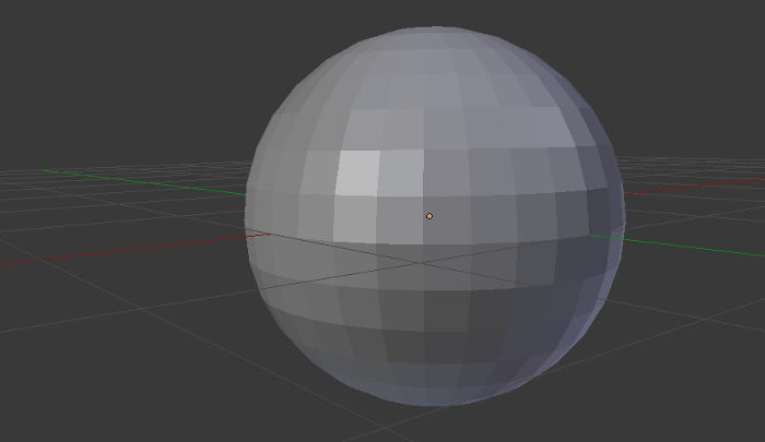
The virtual world differs from the real one in one major way: nothing is continuous, and everything is discrete. For example, you can’t display a perfect circle on a screen. You can approach it by drawing a regular polygon with a lot of edges: the more edges you have, the more “perfect” is your circle.
In 3D, it’s the same thing and every shape must be approached with the 3D equivalent of a polygon: a polyhedron (a 3D shape in which we only find flat faces ant not curved sides as in a sphere). It’s not surprising when we talk about a shape that is already a polyhedron, like a cube, but it’s something to keep in mind when we want to display other shapes, like a sphere.
Storing a Polyhedron
To guess how to store a polyhedron, we have to remember how such a thing can be identified in maths. You surely already did some basic geometry during your school years. To identify a square, for example, you call it ABCD, with A, B, C and D referring to vertices that make up each corner of the square.
For our 3D engine, it will be the same. We will begin by storing each vertex of our shape. Then, this shape will list its faces, and each face will list its vertices.
To represent a vertex, we need the right structure. Here we create a class to store the coordinates of the vertex.
var Vertex = function(x, y, z) {
    this.x = parseFloat(x);
    this.y = parseFloat(y);
    this.z = parseFloat(z);
};
Now a vertex can be created like any other object:
var A = new Vertex(10, 20, 0.5);
Next, we create a class representing our polyhedron. Let’s take a cube as an example. The definition of the class is below, with the explanation right after.
var Cube = function(center, size) {
    // Generate the vertices
    var d = size / 2;

    this.vertices = [
        new Vertex(center.x - d, center.y - d, center.z + d),
        new Vertex(center.x - d, center.y - d, center.z - d),
        new Vertex(center.x + d, center.y - d, center.z - d),
        new Vertex(center.x + d, center.y - d, center.z + d),
        new Vertex(center.x + d, center.y + d, center.z + d),
        new Vertex(center.x + d, center.y + d, center.z - d),
        new Vertex(center.x - d, center.y + d, center.z - d),
        new Vertex(center.x - d, center.y + d, center.z + d)
    ];

    // Generate the faces
    this.faces = [
        [this.vertices[0], this.vertices[1], this.vertices[2], this.vertices[3]],
        [this.vertices[3], this.vertices[2], this.vertices[5], this.vertices[4]],
        [this.vertices[4], this.vertices[5], this.vertices[6], this.vertices[7]],
        [this.vertices[7], this.vertices[6], this.vertices[1], this.vertices[0]],
        [this.vertices[7], this.vertices[0], this.vertices[3], this.vertices[4]],
        [this.vertices[1], this.vertices[6], this.vertices[5], this.vertices[2]]
    ];
};
Using this class, we can create a virtual cube by indicating its center and the length of its edges.
var cube = new Cube(new Vertex(0, 0, 0), 200);
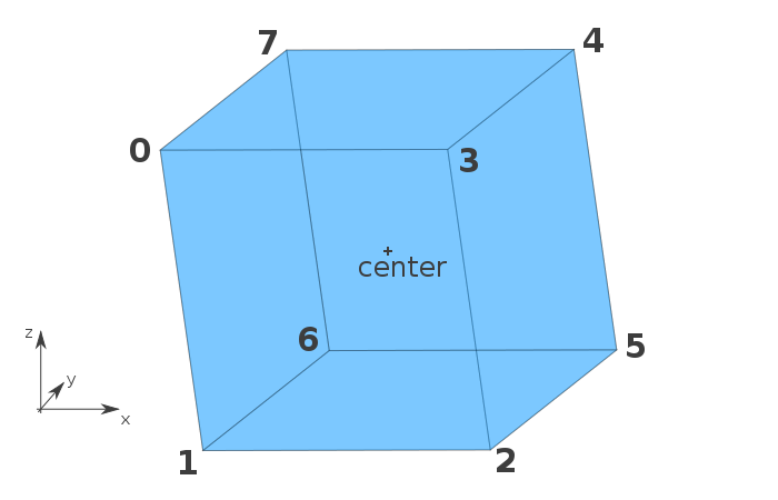
The constructor of the Cube class begins by generating the vertices of the cube, calculated from the position of the indicated center. A schema will be clearer, so see below the positions of the eight vertices we generate:
Then, we list the faces. Each face is a square, so we need to indicate four vertices for each face. Here I chose to represent a face with an array but, if you needed, you could create a dedicated class for that.
When we create a face, we use four vertices. We don’t need to indicate their position again, as they are stored in the this.vertices[i] object. It’s practical, but there is another reason why we did that.
By default, JavaScript tries to use the least amount of memory possible. To achieve that, it doesn’t copy the objects that are passed as functions arguments or even stored into arrays. For our case, it’s perfect behavior.
In fact, each vertex contains three numbers (their coordinates), plus several methods if we need to add them. If, for each face, we store a copy of the vertex, we will use a lot of memory, which is useless. Here, all we have are references: the coordinates (and other methods) are stored once, and only once. As each vertex is used by three different faces, by storing references and not copies, we divide the required memory by three (more or less)!
Do We Need Triangles?
If you have already played with 3D (with software like Blender for example, or with libraries like WebGL), maybe you have heard that we should use triangles. Here, I’ve chosen to not use triangles.
The reason behind this choice is that this article is an introduction to the topic and we will be displaying basic shapes like cubes. Using triangles to display squares would be more of a complication than anything else in our case.
However, if you plan to build a more complete renderer, then you need to know that, in general, triangles are preferred. There are two main reasons for this:
- Textures: to display images on faces we need triangles, for some mathematic reasons;
- Weird faces: three vertices are always in the same plane. However, you can add a fourth vertex that isn’t in the same plane, and you can create a face joining these four vertices. In such a case, to draw it, we don’t have choice: we must split it into two triangles (just try with a sheet of paper!). By using triangles, you keep the control and you choose where the split occurs (thanks Tim for the reminder!).
Acting on a Polyhedron
There is another advantage in storing references instead of copies. When we want to modify a polyhedron, using such a system will also divide the needed number of operations by three.
To understand why, let’s recall once again our math class. When you want to translate a square, you don’t really translate it. In fact, you translate the four vertices, and you join the translations.
Here, we will do the same: we won’t touch the faces. We apply the wanted operation on each vertex and we’re done. As faces use references, the coordinates of the faces are automatically updated. For instance, see how we can translate our previously created cube:
for (var i = 0; i < 8; ++i) {
    cube.vertices[i].x += 50;
    cube.vertices[i].y += 20;
    cube.vertices[i].z += 15;
}
Rendering an Image
We know how to store 3D objects and how to act on them. Now it’s time to see how to view them! But, first we need a small background in the theory, in order to understand what we’re going to do.
Projection
Currently, we store 3D coordinates. However, a screen can only display 2D coordinates so we need a way to transform our 3D coordinates into 2D ones: that’s what we call a projection in math. The 3D to 2D projection is an abstract operation made by a new object called a virtual camera. This camera takes a 3D object and converts its coordinates into 2D ones, to send them to the renderer which will display them on the screen. We will assume here that our camera is placed at the origin of our 3D space (so its coordinates are (0,0,0)).
Since the beginning of this article we’ve talked about coordinates, represented by three numbers: x, y and z. But to define coordinates, we need a basis: is z the vertical coordinate? Does it go to the top or to the bottom? There is no universal answer, and no convention, as the fact is that you can choose whatever you want. The only thing you have to keep in mind is that when you act on 3D objects, you have to be consistent, as formulas will change depending on it. In this article, I chose the basis you can see in the schema of the cube above: x from left to right, y from back to front and z from bottom to top.
Now, we know what to do: we have coordinates in the (x,y,z) basis and, to display them, we need to convert them into coordinates in the (x,z) basis: as it’s a plane, we will be able to display them.
There isn’t only one projection. Worse, there exists an infinite number of different projections! In this article we will see two different types of projection, which are in practice the most used ones.
How to Render Our Scene
Before projecting our objects, let’s write the function that will display them. This function accepts as parameters an array listing the objects to render, the context of the canvas that must be used to display the objects, and other details needed to draw the objects at the right place.
The array can contain several objects to render. These objects have to respect one thing: having a public property named faces that is an array listing all the faces of the object (like our previously created cube). These faces can be anything (square, triangle, or even a dodecagon, if you want): they just need to be arrays listing their vertices.
Let’s look at the code for the function, followed by the explanation:
function render(objects, ctx, dx, dy) {
    // For each object
    for (var i = 0, n_obj = objects.length; i < n_obj; ++i) {
        // For each face
        for (var j = 0, n_faces = objects[i].faces.length; j < n_faces; ++j) {
            // Current face
            var face = objects[i].faces[j];

            // Draw the first vertex
            var P = project(face[0]);
            ctx.beginPath();
            ctx.moveTo(P.x + dx, -P.y + dy);

            // Draw the other vertices
            for (var k = 1, n_vertices = face.length; k < n_vertices; ++k) {
                P = project(face[k]);
                ctx.lineTo(P.x + dx, -P.y + dy);
            }

            // Close the path and draw the face
            ctx.closePath();
            ctx.stroke();
            ctx.fill();
        }
    }
}
This function deserves some explanation. More precisely we need to explain what is this project() function, and what are these dx and dy arguments. The rest is basically nothing other than listing the objects, then drawing each face.
As its name suggests, the project() function is here to convert 3D coordinates into 2D ones. It accepts a vertex in 3D space and returns a vertex in the 2D plane that we could define as below.
var Vertex2D = function(x, y) {
    this.x = parseFloat(x);
    this.y = parseFloat(y);
};
Instead of naming the coordinates x and z I chose here to rename the z coordinate into y, to maintain the classical convention we often find in 2D geometry, but you can keep z if you prefer.
The exact content of project() is what we will see in the next section: it depends on the type of projection you choose. But whatever this type is, the render() function can be kept as it is now.
Once we have coordinates on the plane, we can display them on the canvas, and that’s what we do… with a little trick: we don’t really draw the actual coordinates returned by the project() function.
In fact, the project() function returns coordinates on a virtual 2D plane, but with the same origin than the one we defined for our 3D space. However, we want the origin to be at the center of our canvas, that’s why we translate the coordinates: the vertex (0,0) is not at the center of the canvas, but (0 + dx,0 + dy) is, if we choose dx and dy wisely. As we want (dx,dy) to be at the center of the canvas, we don’t have really the choice and we define dx = canvas.width / 2 and dy = canvas.height / 2.
Finally, the last detail: why are we using -y and not y directly? The answer is in our choice of basis: the z axis is directed to the top. Then, in our scene, a vertice with a positive z-coordinate will move up. However, on the canvas, the y axis is directed to the bottom: a vertice with a positive y-coordinate will move down. That’s why we need to define the canvas’ y-coordinate on the canvas as the reverse of the z-coordinate of our scene.
Now that the render() function is clear, it’s time to looks at project().
Orthographic View
Let’s begin with orthographic projection. As it’s the simplest, it’s perfect to understand what we’ll do.
We have three coordinates, and we want only two. What’s the simplest thing to do in such a case? Remove one of the coordinates. And that’s what we do in orthographic view. We will remove the coordinate that represents the depth: the y coordinate.
function project(M) {
    return new Vertex2D(M.x, M.z);
}
You can now test all the code we wrote since the beginning of this article: it works! Congratulations, you just displayed a 3D object on a flat screen!
This function is implemented in the live example below, where you can interact with the cube by rotating it with your mouse.
See the Pen 3D Orthographic View by SitePoint (@SitePoint) on CodePen.
Sometimes, an orthographic view is what we want, as it has the advantage of preserving the parallels. However, it’s not the most natural view: our eyes don’t see like that. That’s why we will see a second projection: the perspective view.
Perspective View
The perspective view is a bit more complex than the orthographic one, as we need to do some calculations. However, these calculations are not so complicated and you just need to know one thing: how to use the intercept theorem.
To understand why, let’s look at a schema representing the orthographic view. We projected our points on a plane in an orthogonal way.
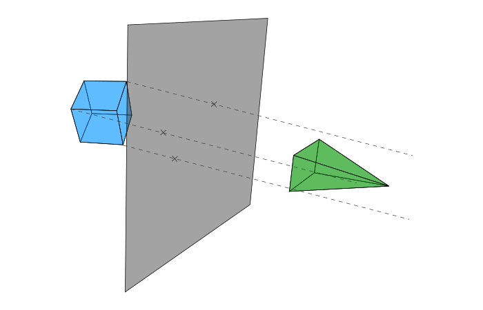
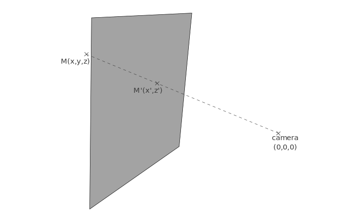
But, in real life, our eyes act more like on the following schema.
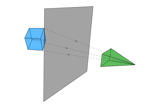
Basically we have then two steps:
- We join the original vertex and the origin of the camera;
- The projection is the intersection between this line and the plane.
Contrary to the orthographic view, the exact location of the plane here is important: if you place the plane far from the camera, you won’t obtain the same effect than if you place it close to it. Here we place it at the distance d from the camera.
Starting from a vertex M(x,y,z) in the 3D space, we want to calculate the coordinates (x',z') of the projection M' on the plane.
To guess how we will calculate these coordinates, let’s take another point of view and see the same schema as above, but seen from the top.
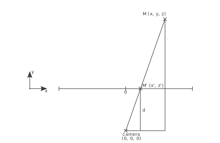
We can recognize a configuration used in the intercept theorem. On the schema above, we know some values: x, y and d, among others. We want to calculate x' so we apply the intercept theorem and obtain this equation: x' = d / y * x.
Now, if you look at the same scene from a side, you get a similar schema, allowing you to obtain the value of z' thanks to z, y and d: z' = d / y * z.
We can now write the project() function using the perspective view:
function project(M) {
    // Distance between the camera and the plane
    var d = 200;
    var r = d / M.y;

    return new Vertex2D(r * M.x, r * M.z);
}
This function can be tested in the live example below. Once again, you can interact with the cube.
See the Pen 3D Perspective View by SitePoint (@SitePoint) on CodePen.
Closing Words
Our (very basic) 3D engine is now ready to display any 3D shape we want. There are some things you could do to enhance it. For example, we see every face of our shapes, even the ones at the back. To hide them, you could implement back-face culling.
Also, we didn’t talk about textures. Here, all our shapes share the same color. You can change that by, for example, adding a color property in your objects, to know how to draw them. You can even choose one color per face without changing a lot of things. You can also try to display images on the faces. However, it’s more difficult and detailing how to do such a thing would take a whole article.
Other things can be changed. We placed the camera at the origin of the space, but you can move it (a change of basis will be needed before projecting the vertices). Also, vertices placed behind the camera are here drawn, and that’s not a thing we want. A clipping plane can fix that (easy to understand, less easy to implement).
As you see, the 3D engine we built here is far to be complete, and it’s also my own interpretation. You can add your own touch with other classes: for example, Three.js uses a dedicated class to manage the camera and the projection. Also, we used basic math to store the coordinates, but if you want to create a more complex application and if you need, for instance, to rotate a lot of vertices during a frame, you won’t have a smooth experience. To optimize it, you will need some more complex math: homogeneous coordinates (projective geometry) and quaternions.
If you have ideas for your own improvements to the engine, or have built something cool based on this code, please let me know in the comments below!
Frequently Asked Questions (FAQs) about Building a 3D Engine in JavaScript
What are the prerequisites for building a 3D engine in JavaScript?
To build a 3D engine in JavaScript, you need a solid understanding of JavaScript and its concepts. Familiarity with HTML and CSS is also beneficial. Knowledge of 3D mathematics, including vectors, matrices, and quaternions, is crucial. Understanding the basics of computer graphics, such as rendering pipelines, shaders, and texture mapping, will also be helpful.
How can I start learning 3D mathematics for JavaScript 3D engine development?
There are several resources available online to learn 3D mathematics. Websites like Khan Academy offer courses on linear algebra and vector calculus, which are fundamental to understanding 3D mathematics. Books like “3D Math Primer for Graphics and Game Development” can also be helpful.
What are the best libraries for building a 3D engine in JavaScript?
Three.js and Babylon.js are two of the most popular libraries for building 3D engines in JavaScript. Both libraries provide a high-level interface to WebGL, making it easier to create complex 3D scenes. They also offer extensive documentation and community support.
How can I optimize my JavaScript 3D engine for better performance?
There are several ways to optimize your 3D engine for better performance. One way is to minimize the number of draw calls by using techniques like instancing and batching. Another way is to reduce the amount of data sent to the GPU by using compressed textures and geometry. You can also optimize your shaders for better performance.
How can I handle user input in my JavaScript 3D engine?
Handling user input in a JavaScript 3D engine typically involves listening for keyboard and mouse events. You can use the ‘addEventListener’ method provided by the browser to listen for these events. You can then use the event data to control the camera or other elements in your 3D scene.
How can I add lighting to my JavaScript 3D engine?
Adding lighting to a JavaScript 3D engine involves creating light sources and implementing a shading model. The light sources can be directional, point, or spotlights. The shading model, which determines how surfaces respond to light, can be simple (like Lambertian shading) or complex (like physically-based rendering).
How can I add textures to my JavaScript 3D engine?
Adding textures to a JavaScript 3D engine involves loading image files, creating texture objects, and mapping them onto geometry. You can use the ‘Image’ object provided by the browser to load images. You can then create texture objects using the ‘gl.createTexture’ method provided by WebGL.
How can I add animations to my JavaScript 3D engine?
Adding animations to a JavaScript 3D engine involves changing the properties of objects over time. You can use the ‘requestAnimationFrame’ method provided by the browser to create a loop that updates the properties of objects at a consistent rate. You can then use interpolation techniques to smoothly transition between different states.
How can I handle collisions in my JavaScript 3D engine?
Handling collisions in a JavaScript 3D engine typically involves implementing a collision detection algorithm. This can be as simple as checking for overlaps between bounding boxes or as complex as checking for intersections between complex geometries. Once a collision is detected, you can then respond by changing the properties of the colliding objects.
How can I debug my JavaScript 3D engine?
Debugging a JavaScript 3D engine can be challenging due to the complexity of 3D graphics. However, tools like the WebGL Inspector and the Chrome DevTools can be very helpful. These tools allow you to inspect the state of the WebGL context, view the contents of buffers and textures, and step through your shaders.